21
6. Connection to power supply
After interconnecting all PowerPlex
®
components of your system via a CAN bus cable, the installation only has to
be connected to electrical power supply. PowerPlex
®
is suitable for both DC 12 V and DC 24 V.
Caution
• Please make sure that all electrical installations were carried out in accordance with EN ISO
10133.
• Please make sure that the power supply is disconnected and protected against inadvertent re-
connection during the works on the system.
• Please avoid large differences between the lengths of the (+) and (-) cables.
Connecting the device
The 2-pole connector (X1) are used for connecting the PowerPlex
®
Compact Module to the power supply (DC 12
V/DC 24 V). A mating connector ensures easy connection.
Caution
The device has to be directly connected with the power supply via a suitable overcurrent protection. It
must not be linked up within the system via some other PowerPlex
®
component to ensure impeccable
start-up of the entire system.
Protection and cable cross sections
Suitable elements for overcurrent protection must be used to protect the PowerPlex
®
components. The current
ratings of the circuit breaker should correspond to the max. expected total current of all outputs of the PowerPlex
®
component to be protected.
In the event of 60 A this corresponds to a cable cross section of 16 mm² connected to the U
Batt
+ (1.1) of the
2-pole connector. Since Ground (GND
O
) of the loads on outputs (X2: O1 - O10 and X3: O1 - O4) is led externally,
a cable cross-section of 4 mm² is sufficient for the U
Batt
- (1.2) of the 2-pole connector.
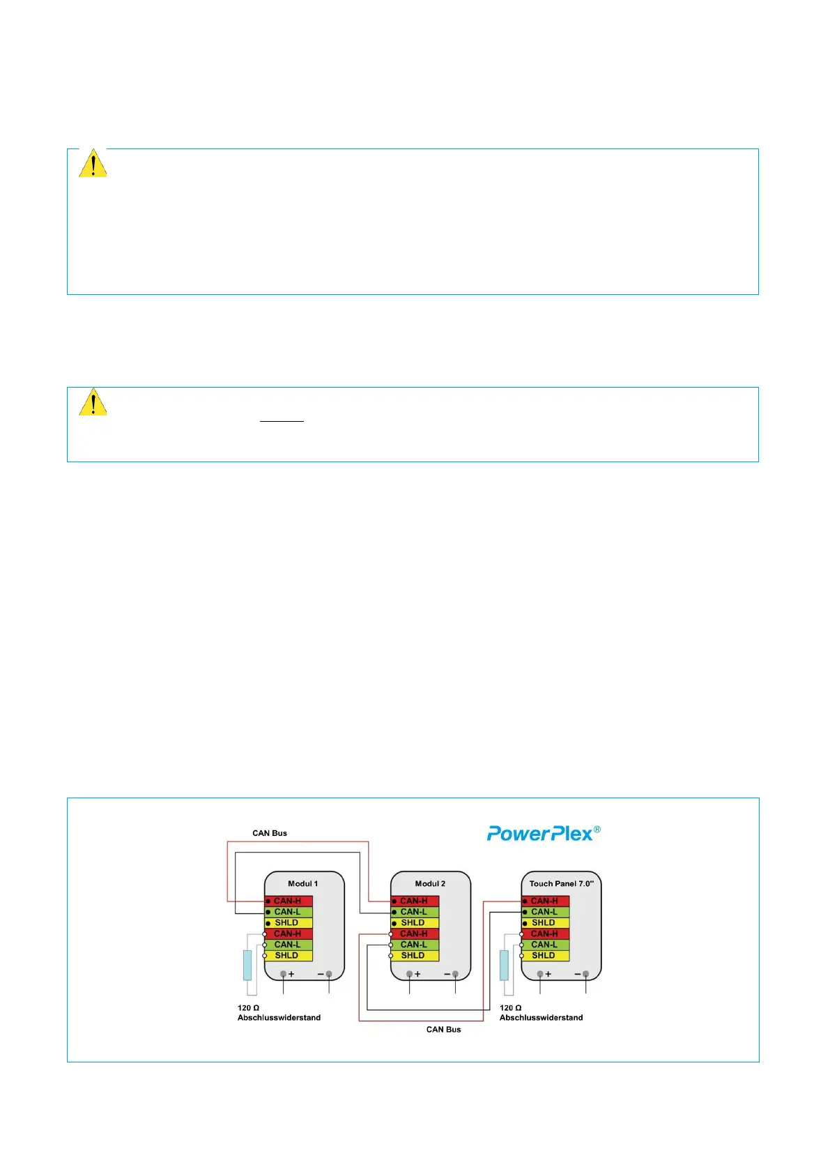
7. Integration of the device in the CAN bus network
To set up the CAN bus network all PowerPlex
®
components are connected with each other (→ Fig. 10).
A CAN bus must be terminated with a 120 Ω resistor at the beginning and end. Bus terminating resistors are not
installed in the Compact Module. If the device is operated as the first or last participant on the CAN bus, a 120 Ω
terminating resistor has to be placed between the pins 3.1 and 3.2 of the 22-pole connector (→ Table 13).
Fig. 10: Connection of the PowerPlex® components in the CAN bus system