Mark the intended installation site following the installation dimensions
Drill the mounting holes into the wall with an adequate tool.
Depending on the accessibility of the cable connections we recommend to connect all cables (current,
CAN etc.) before mounting the device.
Important: A cable connection must only be established if the main switch is OFF. Check the cables
with regard to correct polarity and ensure that the max. permissible operating voltage is not exceeded.
Please do not forget the terminating resistor if the device is the first or last participant on the CAN bus.
Table 9: Mounting of the device
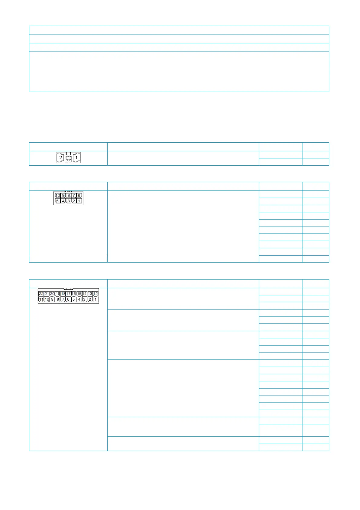
Pin assignment
The pins of the PowerPlex
®
Compact Module are on the bottom side. The pin assignment is shown in Table 10.
Please note that the mating connectors are not included in the delivery scope as standard.
voltage supply
(DC 12V/24V; DC 9 … 32V)
Table 10: Pin assignment on the 2-pole connector (X1)
10 A outputs, dimmable
(motor function [H1/H2]: O1 & O2, O6 & O7; high current function: 20
A via parallel connection; GND
O
must be connected externally.)
Table 11: Pin assignment on the 10-pole connector (X2)
CAN I: PowerPlex® CAN, galvanically isolated
CAN II: galvanically isolated
10 A outputs, dimmable
(note: parallel connection possible; GND
O
must be connected
externally.)
multifunctional inputs
(note: when monitoring the battery, it must be ensured that PLUS/
MINUS are correctly connected.)
GND for multifunctional inputs
(note: only use GND
I
for multifunctional inputs (X3: I1 – I8), not for
GND
O
of the load outputs (X2: O1 – O10; X3: O1 – O4)
Tabel 12: Pin assignment on the 22-pole connector (X3)