18
5.3. General notes on wiring
The selection of the correct cable types is important for the reliable power distribution, control and monitoring by
means of a PowerPlex
®
system. Please ensure to use cables of superior quality with the suitable cross sections
to avoid voltage drops. Please also so the separate chapter 7 concerning the integration of the device into the
CAN bus network.
The cables should be laid very carefully to achieve the maximum performance of the PowerPlex
®
installation.
Table 8 gives general hints which must be observed regarding wiring of a PowerPlex
®
system and the connected
loads.
The cables should not be kinked or bent sharply. Please provide sufficient bending radii.
Cables must be protected against damages and heat. Avoid the proximity to moveable or hot parts and
to machines.
Cables should be secured by means of brackets or cable clips. Excessive cable lengths should be
disposed of appropriately.
Depending on the site of the cables, waterproof bushings might be useful.
Ensure a suitable strain relief.
Check cables about intact insulation, above all after cable laying.
Table 8: General notes on wiring
If AC and DC current is used for installation, an adequate insulation must be ensured.
Note
Please do not forget the 120 Ω terminating resistor when the PowerPlex
®
Compact Module is
connected as first and/or last participant on the CAN bus.
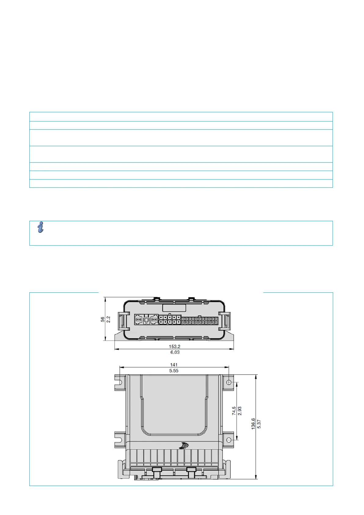
5.4.
Required installation dimensions - mounting cut-out
The PowerPlex
®
Compact Module are meant for front panel mounting. The modules are screwed onto the
mounting plate from the front, e.g. in the side trim panel. The required dimensions are shown in Fig. 8.