15
4.2. Scope of delivery
Standard scope of delivery of the PowerPlex
®
Compact Module is without accessories.
For completion we recommend the following accessories:
XPP-CP-130
(contains a 2-, 10- and 22-pole connector, 10 x crimp contacts 14-16 AWG and
22 x crimp contacts 16 AWG))
4.3. Inputs, outputs and interfaces
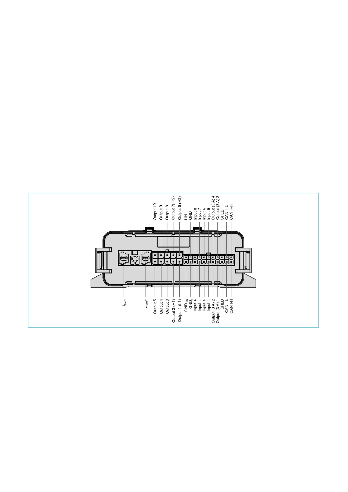
Fig. 7 shows an overview of the terminals and interfaces of the PowerPlex
®
Compact Module.
Fig. 7: Pin assignment of the PowerPlex® Compact Module
Explanation:
• Inputs (X3: I1 - I8) are multifunctional inputs which can be configured as a digital or analogue input.
• GND
I
are ground terminals only for the multifunctional inputs (X3: I1 - I8). The outputs must be connected
to external ground GND
O
.
• Outputs are dimmable outputs
o with max. 10 A continuous current, (X2:O1 - O10)
o with max. 3 A continuous current, (X3: O1 - O4)
• Outputs (X2: O1 & O2; O6 & O7) can be used for switching H-bridges (motor function).
• U
batt
+ and U
batt
- are for the connection of the power supply
• CAN-H, CAN-L, SHLD are the interfaces to the CAN buses (CAN I: PowerPlex® CAN; CAN II: other CAN
bus)