11
3. PowerPlex
®
system: General
3.1. PowerPlex
®
Modules
PowerPlex
®
modules are the key components of a PowerPlex
®
network. According to the CAN bus terminology
they are the “nodes” of the network and form the points of switching, transmission and control.
PowerPlex
®
for DC system include high-end power semi-conductors with integral protective elements for switching
and protection of electrical loads. The modules are free of mechanical components and thus insusceptible to wear
and shock and vibration resistant.
E-T-A offers various PowerPlex
®
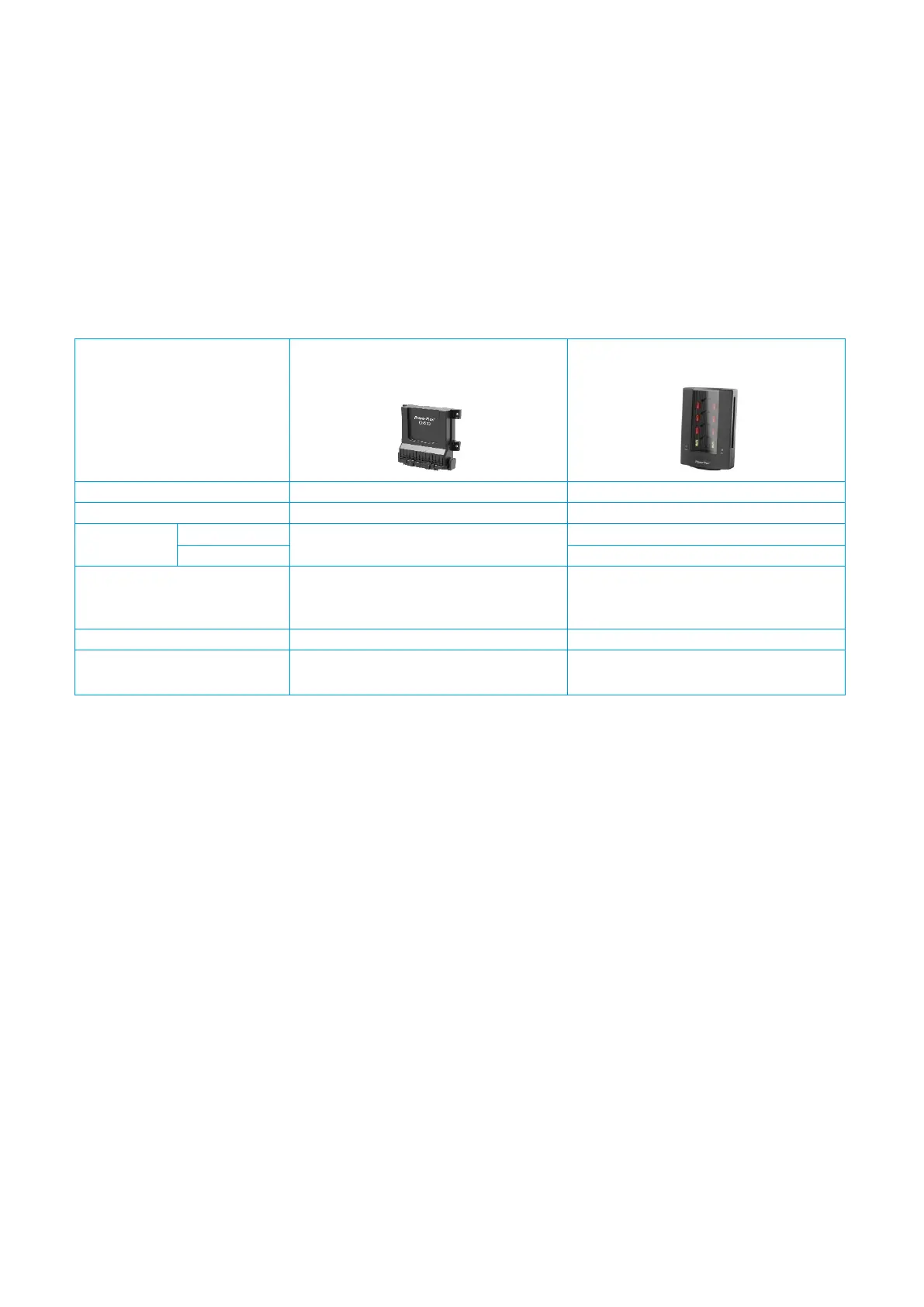
modules for DC 12 V and DC 24 V systems. gives an example of the difference
between two modules.
Table 3: Different PowerPlex® Modules
3.2. PowerPlex
®
CAN Bus
A PowerPlex
®
network can embrace up to 30 different PowerPlex
®
modules. The smallest PowerPlex
®
system
would consist of two modules communicating via the CAN bus cable (see Fig. 4).
The loads controlled by the modules - in this case a light and bilge pump - are normally installed at some place in
the vehicle which may not be necessarily close to the input signal. The decentralised control structure of
PowerPlex
®
allows monitoring and switching of the devices anywhere on the vehicle or boat from any chosen
installation site.
A level sensor monitors the bilge and supplies the analog information on module 1. From there the information is
transferred to module 2 via the CAN bus. As soon as the measured analog input value (i.e. the “pumping level”)
has exceeded a pre-set limit value , module 2 will send a switch command to the load (i.e. the “bilge pump”) so
as to switch on the pump and to reduce the water level of the bilge back to an acceptable level. The status
information of the bilge pump will be sent back to module 1 to switch on the display “bilge pump running”.
In addition, module 2 monitors the position of a light switch – ON or OFF – at one of the digital inputs and sends
the switching signal to module 1, which switches the light ON or OFF depending on the switching status.