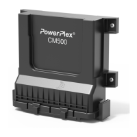
Fig. 4: Two PowerPlex® modules connected via CAN bus cable
An example demonstrates the principle of using the sensor and switching signal information at the module inputs
as well as the sending, switching or the display of commands to the outputs of the same or a different module.
A typical PowerPlex
®
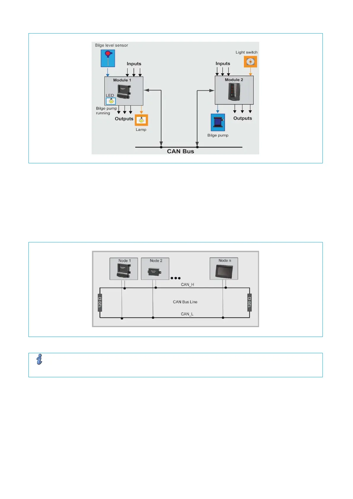
control system will of course connect a much higher number of modules and their inputs
and outputs which will be distributed over the entire vehicle. Fig. 5 shows the electrical connection of several
PowerPlex
®
modules in a serial CAN bus topology. Each module must be connected to the DC voltage supply
and the CAN bus.
Note
The first and last Modules of the CAN bus topology must be connected with a 120 Ω terminating resistor
between the CAN high and CAN low signals. This helps avoiding interferences on the bus.