UMPETHA 082009/072010.014
Installing the limit actuator
(Mandatory before programming)
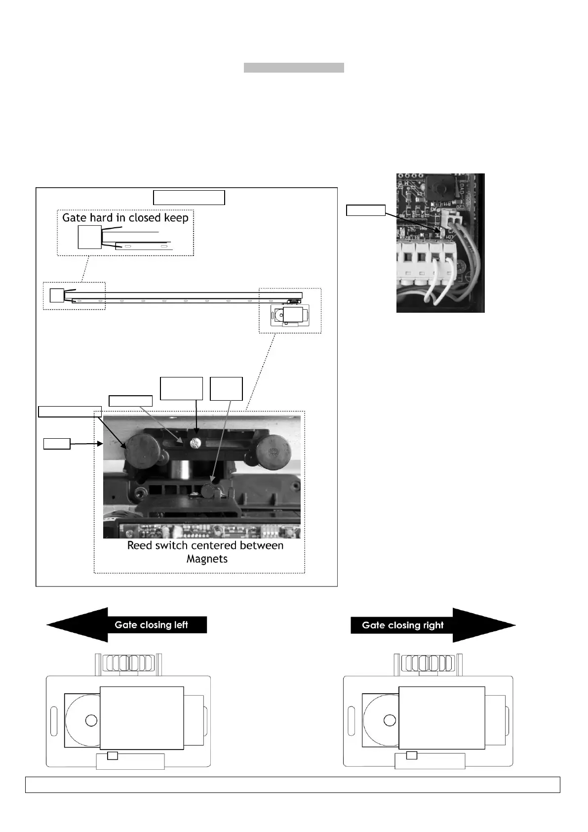
1. Push the gate up against the closed stopper/keep.
2. Place magnetic actuator on top of the rack where it is half way across the reed switch. See below
3. Remove the rack screw (Holding the nylon teeth to the steel angle) closest to the middle of the slot in the actuator.
4. Replace this screw with the longer screw provided with the actuator.
5. Adjust the stopping position by sliding the actuator sideways. Check the closed limit LED while doing this.
After programming the run-time (page 15) the gate should stop a minimum of 10-20mm from the mechanical end stop. Adjust the
actuator if necessary.