BRAKES - REAR MECHANICAL
Page K-15
Repair and Service Manual
Read all of Section B and this section before attempting any procedure. Pay particular attention to all Notes, Cautions and Warnings
At the spherical nut, adjust the free travel as noted
above.
Drive again and brake aggressively 10 times.
Repeat the previous step(s) until the pedal free travel
does not change during the aggressive braking.
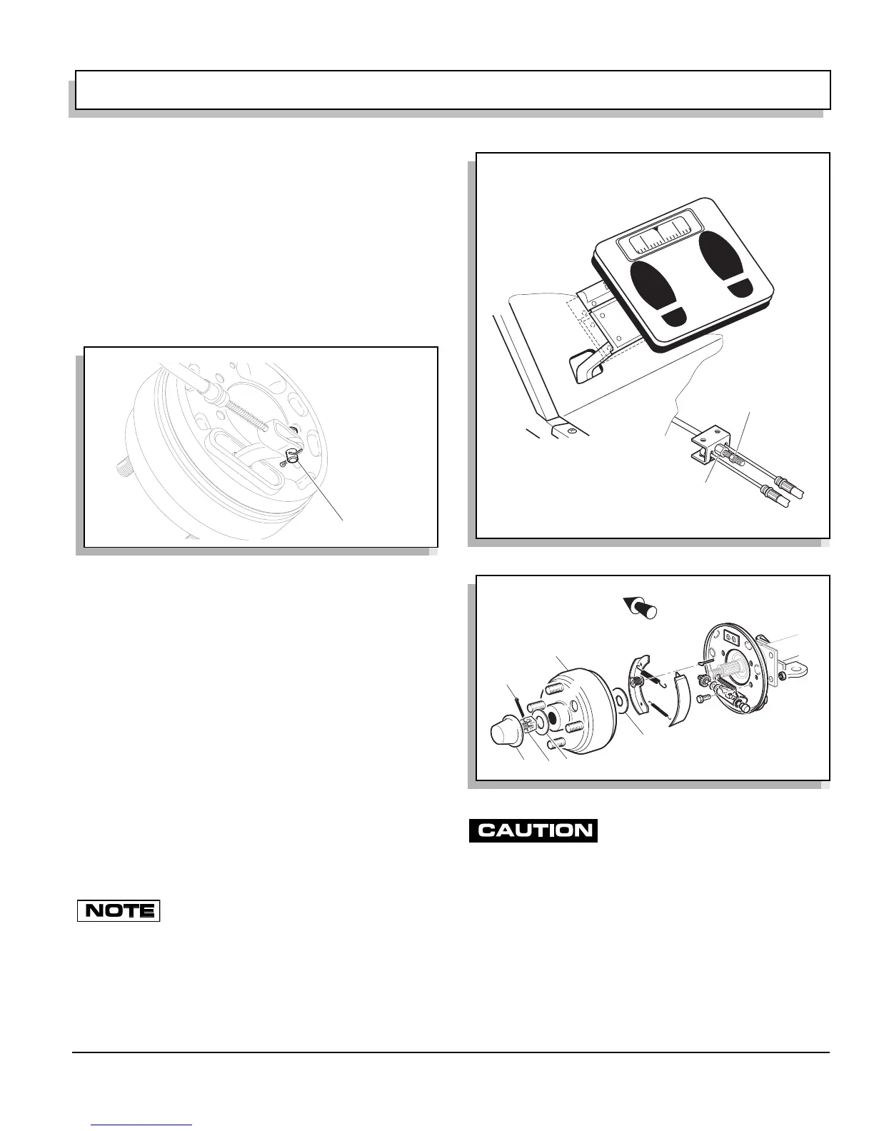
Check to see that the clevis pins attaching the brake
cables to the brake levers are loose (Ref Fig. 19 on page
K-15). If they are not loose, inspect system again and
correct as required. If the clevis pins are loose, tighten
jam nut to 10 - 11 ft. lbs. (14 - 15 Nm) at the spherical nut.
The parking brake latching force can be checked as veri-
fication after setting brake pedal free travel. To check
parking brake latching force, place a ‘bathroom’ scale on
the service and parking brake pedals. Using both feet
press the scale down against the parking brake pedal
until it latches. The parking brake should latch between
65 and 75 lbs. (29 - 34 kg) indicated on the scale (Ref
Fig. 20 on page K-15).
Perform the Periodic Brake Performance Test as
described on page K-10 and return the vehicle to service
if brake performance is satisfactory.
Brake Drum Removal and Installation
Remove the dust cap (1) to gain access to the castel-
lated nut (2) and the cotter pin (3) (Ref Fig. 21 on page K-
15).
Remove the cotter pin and castellated nut as shown.
Do not apply the brake when removing the nut
as the shoes may not fully retract preventing
removal of the brake drum.
Remove washer (4).
Slide the brake drum (5) from the axle shaft. If required,
tap the drum with a plastic faced hammer to loosen it
from the axle shaft or use drum puller (P/N 15947-G1).
Use care when raising the adjuster arm.
Too much force will damage the adjust-
er and require that both wheel brake assemblies be replaced.
If the drum does not slide from the brake assembly, the
brake shoes must be retracted. Rotate the hub so that
the hole in the drum is in the six o’clock position which is
directly over the brake mechanism. Use a small straight
blade screwdriver to raise the adjuster arm just above
the star wheel.
Loosen the star wheel to retract the brake shoes and
remove the brake drum.
Fig. 19 Check Clevis Pins
Clevis Pin Loose?
Fig. 20 Checking Parking Brake Latching Pressure
Fig. 21 Brake Assembly
If required adjust spherical nut
to achieve correct parking brake
latching pressure of 65 - 75 lbs.
(29 - 34 kg).
Loosen Jam Nut
Use a 'bathroom' scale
to confirm the latching force
required to engage and latch
the parking brake.
65 70 75
Front of Vehicle
1
2
3
4
5
6
 Loading...


