FRONT SUSPENSION AND STEERING
Page E-13
Repair and Service Manual
Read all of Section B and this section before attempting any procedure. Pay particular attention to all Notes, Cautions and Warnings
page E-15. Anchor in vice by clamping on the mounting
ears of the rack and pinion unit.
Slide a small straight blade screwdriver between lip of
seal and pinion and pry top portion of seal up to remove
(Ref Fig. 16 on page E-13).
Use screwdriver to lift inner portion of seal up and off pin-
ion.
Check pinion surface for roughness and sand lightly if
needed.
Wipe bore clean and lubricate pinion and lip of seal with
grease.
The bore has a positive stop to correctly locate
the seal during installation.
Place seal over pinion and tap carefully with socket and
hammer to start seal straight in bore. Drive seal fully into
bore until it stops and wipe clean of any excess grease.
Attach rack and pinion unit to front axle. See ‘Rack and
Pinion Unit Replacement’ on page E-15.
Spindle Replacement
Tool List Qty. Required
Needle nose pliers ...................................................... 1
Wrench, 11/16"............................................................ 1
Ball joint separator ...................................................... 1
Plastic faced hammer ................................................. 1
Wrench, 3/4" ............................................................... 1
Socket, 3/4", 1/2" drive................................................ 1
Socket, 11/16", 1/2" drive............................................ 1
Torque wrench, 1/2" drive, ft. lbs................................. 1
The spindle bearings are designed to
be used "dry". Lubrication attracts dirt
and will ruin the bearings. Do not apply grease to the spindle
bearings.
Loosen front wheel. Lift and support front of vehicle per
SAFETY section and remove front wheel.
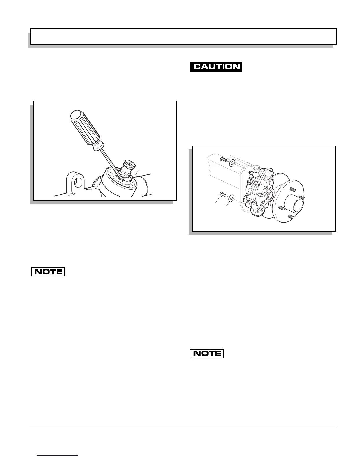
If vehicle is equipped with front disc brakes, remove cali-
per by removing bolts (1) and washers (2). Secure the
caliper with a length of wire, cord or wire tie to relieve any
tension that would be created by the caliper hanging
from the brake line (Ref Fig. 17 on page E-13).
To remove tie rod, loosen lock nut (2) until tie rod ball
joint (3) threads are protected (Ref Fig. 18 on page E-
14). Using a ball joint separator as a lever, apply pres-
sure to ball joint and tap nut with plastic faced hammer to
release tie rod from spindle arm (4). Remove nut from tie
rod and tie rod from spindle arm.
If removing passenger side spindle, repeat previous step
for rack ball joint.
Remove lock nut (5) and washer (7) from bolt (6) and dis-
card nut. Pull bolt (6) and washer (8) from spindle and
separate spindle from axle. Remove thrust washer (9)
and king pin tube (10) from spindle.
Spindle installation is the reverse order of disassembly.
The thrust washer (9) is located on top of spin-
dle between spindle and front axle.
Tighten new lock nut (5) to 56 - 70 ft. lbs. (75 - 95 Nm)
torque. Check that spindle turns freely on king pin tube
after tightening.
Tighten lock nut (2) to 36 ft. lbs. (50 Nm). Maximum
torque is 50 ft. lbs. (70 Nm).
Install front wheels per WHEELS AND TIRES section
and lower vehicle per SAFETY section.
Fig. 16 Pinion Seal Replacement
Lip of
Seal
Fig. 17 Removing Brake Caliper
ef Rbc 1
2
1
 Loading...


