FRONT SUSPENSION AND STEERING
Page E-12
Repair and Service Manual
Read all of Section B and this section before attempting any procedure. Pay particular attention to all Notes, Cautions and Warnings
Remove lock nut (10) until tie rod ball joint (6) threads
are protected. Using a ball joint separator as a lever,
apply pressure to ball joint and tap nut with plastic faced
hammer to release tie rod from spindle arm. Remove nut
to drop tie rod from spindle arm.
Unscrew tie rod ball joint and jam nut from threaded tube.
To install ball joint, first thread on new jam nut and then,
using measurement made earlier, screw ball joint to pre-
vious location in threaded tube. Set jam nut hand tight.
The distance to center of tie rod ball joint from
jam nut on both ends of threaded tube should
be the same.
Attach tie rod to spindle. The lock nut (10) should be
tightened to a minimum of 36 ft. lbs. (50 Nm) torque.
Maximum torque is 50 ft. lbs. (70 Nm).
Install front wheel(s) per WHEELS AND TIRES section
and lower vehicle per SAFETY section.
A worn tie rod is likely to have caused incorrect wheel
alignment. Check front wheel alignment and adjust if
necessary. See ‘Wheel Alignment’ on page E-3.
Jam nut should be tightened to 36 - 40 ft. lbs. (49 - 54
Nm) torque.
Bellows Replacement
Tool List Qty. Required
Needle nose pliers.......................................................1
Wrench, 11/16"............................................................ 1
Ball joint separator....................................................... 1
Plastic faced hammer.................................................. 1
Tape measure.............................................................. 1
Wrench, 3/4"................................................................ 1
Wire cutters ................................................................. 1
Wire tie, 8" long ...........................................................1
Torque wrench, 1/2" drive, ft. lbs. ................................ 1
Socket, 11/16", 1/2" drive ............................................ 1
To replace bellows (1) (Ref Fig. 15 on page E-12), first
loosen passenger side front wheel and lift and support
front of vehicle per SAFETY section.
Remove passenger side front wheel and turn steering
wheel fully to the left.
Remove rack ball joint (2) and jam nut (3) from rack
extension (4). See ‘Rack Ball Joint Replacement’ on
page E-10.
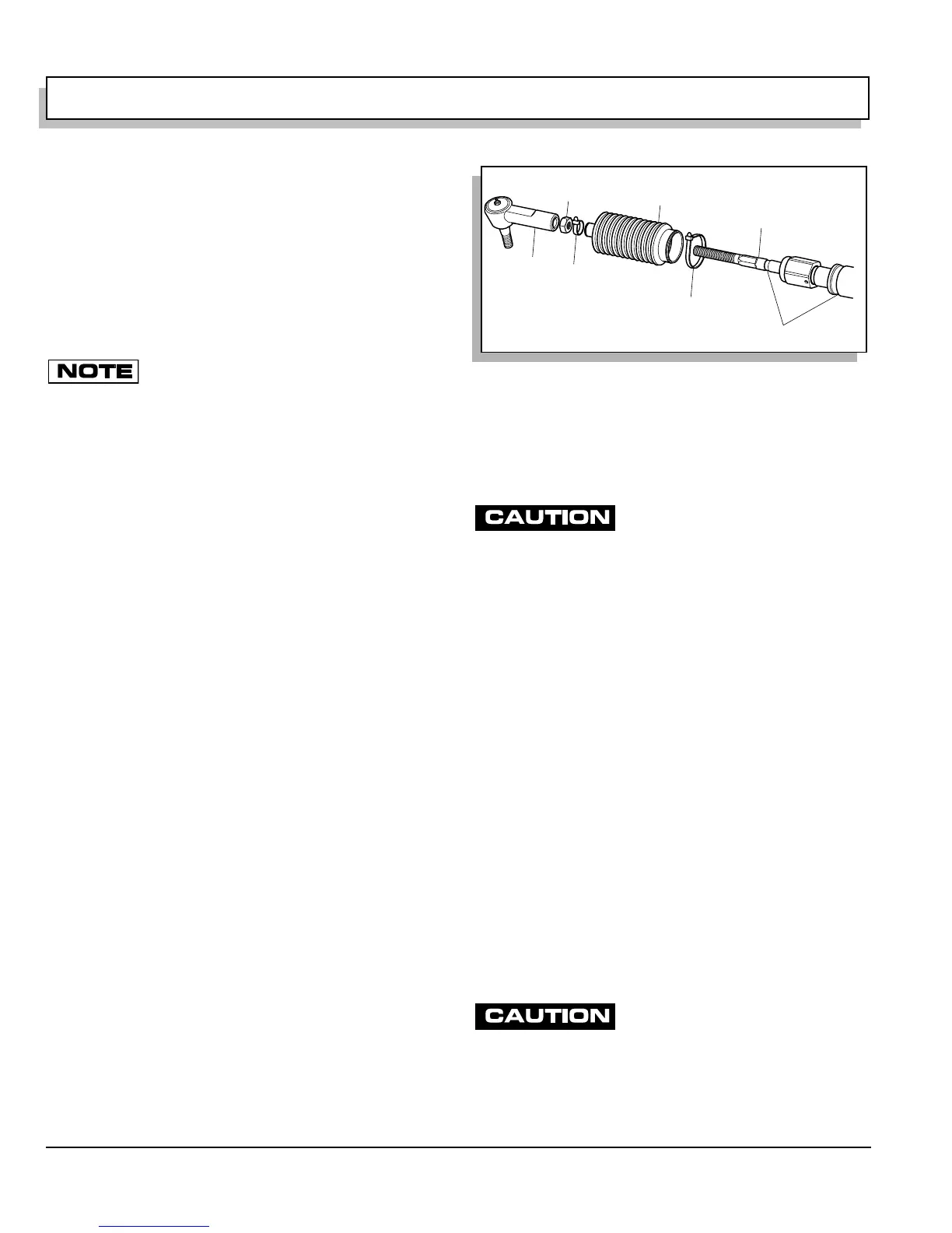
Cut wire ties (5,6) and slide bellows off rack extension.
Install new bellows aligning small end over groove in rack
extension and secure with new wire tie (5). Leave large
end loose until rack extension-to-rack and pinion unit
clearance is checked or adjusted.
Install jam nut (3) and rack ball joint (2) on rack extension
(4) and reattach to spindle arm. See ‘Rack Ball Joint
Replacement’ on page E-10.
After replacing or servicing steering
components, always verify that an 1/8"
gap exists between large hex of rack extension and rack and pin-
ion unit when steering is turned fully to the right forcing passen-
ger spindle arm against front axle.
Check for proper rack extension-to-rack and pinion unit
clearance before tightening jam nut (3) to 35 - 45 ft. lbs.
(47 - 61 Nm) torque. See ‘Checking/Adjusting Rack
Extension-to-Rack and Pinion Unit Clearance’ on page
E-15.
Install passenger side front wheel per WHEELS AND
TIRES section and lower vehicle per SAFETY section.
Check front wheel alignment and adjust if necessary.
See ‘Wheel Alignment’ on page E-3.
Pinion Seal Replacement
Tool List Qty. Required
Vice..............................................................................1
Straight blade screwdriver, small.................................1
Ball peen hammer .......................................................1
Sandpaper, 600 grit ..................................................AR
Shop towel................................................................AR
Wheel bearing grease ..............................................AR
Socket, 1 1/2", 1/2" drive .............................................1
Secure rack and pinion unit in vice by
the mounting ears only. The rack and
pinion unit is made of aluminum and can be damaged if held oth-
erwise.
To access the pinion seal, remove rack and pinion unit
from vehicle. See ‘Rack and Pinion Unit Replacement’ on
Fig. 15 Bellows Replacement
5
1
3
4
2
Grooves
6
 Loading...


