K
BRAKES - FRONT DISC
Page K-21
Repair and Service Manual
Read all of Section B and this section before attempting any procedure. Pay particular attention to all Notes, Cautions and Warnings
SYSTEM DESCRIPTION
To assure correct braking performance, all peri-
odic maintenance, inspections and procedures
must be performed as indicated in the Periodic Service Sched-
ule in Section ‘A’ of this manual. The brake system must be
bled whenever any part of the brake system has been
replaced.
A hydraulic system is used to actuate the front brakes.
The system transmits the power required to activate the
friction surfaces (pads) of the braking system from the
pedal to the individual disc brake hubs at each wheel.
The front hydraulic brake system is designed to operate
only after significant rear brake pressure has been
applied. This is accomplished by activating the master
cylinder after the brake pedal has reached the parking
brake latch position. The lower actuator pivot is con-
nected to the brake pedal by a linkage rod which rotates
to contact the upper actuator pivot. The upper actuator
pivot is connected to a clevis of the master cylinder
plunger. Movement of the plunger hydraulically activates
the caliper pistons forcing the brake pads against the
rotors. With the brake pedal released, the upper actuator
pivot and the plunger returns to the ‘at rest’ position. With
the master cylinder no longer applying hydraulic pres-
sure to the brake pistons, the piston seals retract the pis-
tons permitting the brake pads to float freely against their
guide pins while removing all pressure against the rotors.
MASTER CYLINDER REPLACEMENT
During this process, it is likely that
brake fluid will leak from the master cyl-
inder. Avoid allowing brake fluid to contact the painted body
components of the vehicle. Wipe off immediately.
Removing the front shield may improve access (See
BODY)
To remove the master cylinder:
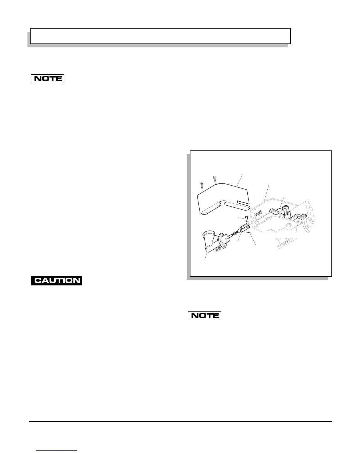
Remove the bolts securing the brake actuator assembly
housing cover and remove cover. The clevis pin joining
the brake cylinder clevis and the upper actuator pivot
must be removed by removing the cotter pin and discard-
ing. Remove clevis pin (Ref Fig. 1 on page K-21).
Remove the braided brake line from the master cylinder
and allow brake fluid to drain into a container. Do not
reuse old brake fluid. Remove the two nuts, bolts and
washers securing the master cylinder to the brake actua-
tor assembly housing. Install new master cylinder, and
tighten nuts to 12 - 14 ft. lbs (16 - 19 Nm) torque. Install
brake line to new master cylinder and tighten to 15 in.
lbs. (1.7 Nm) torque.
Latch the brake pedal. Rotate and hold the upper actua-
tor pivot against the lower actuator pivot. (Rotate and
hold the upper actuator pivot such that the rectangular
stop tab contacts the lower actuator pivot stop tab.)
Adjust master cylinder clevis until the clevis pin passes
through the upper actuator pivot and the master cylinder
clevis. Tighten jam nut against master cylinder clevis.
Install a new cotter pin. Bleed hydraulic system.
Add clean fresh DOT 3 brake fluid into reservoir and
bleed system per ‘BLEEDING BRAKES’.
BRAKE MASTER CYLINDER FLUID
Hydraulic brake systems must be totally
flushed if the fluid becomes contaminated with
water, dirt or other corrosive chemicals. To flush, bleed the
entire system until all brake fluid has been replaced with fresh
DOT 3 standard automotive brake fluid.
Check Brake Fluid
The brake fluid should be checked at regular intervals
(as specified in the Periodic Service Schedule) or imme-
diately if fluid leaks are found. The easiest way to check
fluid level is to clean the cap with a shop rag and remove
the cap. Check fluid level using a mechanics mirror and a
flashlight. Add fluid if the level has fallen below 1/4" (6.5
mm) from the top of the reservoir and inspect for visible
fluid leaks.
Fig. 1 Master Cylinder Replacement
Ref Mcr 1
Brake Actuator
Assembly Housing
Housing
Cover
Master Cylinder
Clevis pin
Cotter Pin
Clevis
Lower Actuator Pivot
Upper Actuator Pivot
 Loading...


