BRAKES - REAR MECHANICAL
Page K-17
Repair and Service Manual
Read all of Section B and this section before attempting any procedure. Pay particular attention to all Notes, Cautions and Warnings
Be sure that the adjusting screw is
screwed into the star wheel nut until
only 1 - 2 threads are exposed (Ref Fig. 25 on page K-18). If the
brake shoes are replaced, replace the three brake springs and
the adjuster components.
Replace the springs one side at a time, using the other
side as a guide.
Install brake drum as described in ‘Brake Drum Removal
and Installation’.
Repeat on other side of vehicle.
Adjust the brake pedal free travel. See ‘Adjusting Brake
Pedal Free Travel’ on page K-14.
Backing Plate/Entire Wheel Brake Assembly
Removal and Installation
Remove the four bolts (1) and lock nuts (2) securing the
wheel brake backing plate to the flange on the axle tube
(Ref Fig. 23 on page K-17).
Remove the clevis pin securing the brake cable to the
brake lever.
Installation is the reverse of removal. Connect the brake
cable to the wheel brake with the clevis pin installed from
the top down and a new cotter pin. Install the brake
assembly or backing plate to the axle tube flange. Install
new hardware (locknut should only be used once) and
tighten to 23 - 28 ft. lbs (31 - 38 Nm) torque.
Brake Shoe and Adjuster Replacement
It is recommended that when brake shoes are
replaced, the adjusters and springs also be
replaced. It is good practice to do one side at a time, using the
other side for reference.
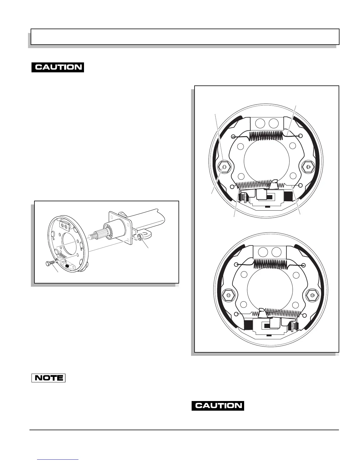
Remove the three brake shoe springs and discard (1, 2,
3). Note the location of the heavy spring and the adjuster
spring (Ref Fig. 24 on page K-17). Hold the shoe clamp
pin (4) and compress and rotate the shoe clamp (5) 90°
to release it from the shoe clamp pin. Remove the brake
shoes, adjusters and remaining components.
Clean the backing plate with a commercial brake cleaner.
Allow to dry completely. Lubricate the friction points of
the shoes and moving anchor with Multi Purpose Grease
(MPG) lubricant (Ref Fig. 22 on page K-16).
Be sure that the adjusting screw is
screwed into the star wheel nut until
only 1 - 2 threads are exposed
Fig. 23 Backing Plate Removal and Installation
1
2
Fig. 24 Brake Shoes and Springs
1
Heavy Shoe Spring
2
3
Light Shoe
Spring
Adjuster
Spring
Shoe
Clamp
Pin
5
Shoe Clamp
4
 Loading...


