BRAKES - REAR MECHANICAL
Page K-19
Repair and Service Manual
Read all of Section B and this section before attempting any procedure. Pay particular attention to all Notes, Cautions and Warnings
ing a thin blade screwdriver between the small hook and
the bracket. Move the hook back and to the side to
release the torsion spring (Ref Fig. 27 on page K-19).
Remove the lock nut (5), the shoulder bolt (6) and
remove the brake pedal.
Inspect the shoulder bolt for corrosion that could cause
binding. This bolt and both bushings (7) must be
replaced with new ones if corrosion or wear is found.
Brake pedal installation is in the reverse order of disas-
sembly. Tighten the nut (5) to 25 - 29 ft. lbs. (34 - 39 Nm)
torque and use a new cotter pin when installing the com-
pensator assembly. Connect brake light wiring harness, if
equipped.
Adjust the brake pedal free travel. See ‘Adjusting Brake
Pedal Free Travel’ on page K-14.
Check for proper brake light operation if equipped.
Parking Brake Catch Bracket Removal and
Installation
Remove the driver side front wheel to gain access to the
brake pedal release mechanism.
To prevent serious injury
death resulting from the
use of worn parking
brake components, to not attempt to re-new worn
components. The catch bracket is a hardened part.
Do not grind or file it as doing so will cause the part to
lose its hardness characteristics. A new part must be
used.
Remove the two bolts (1) and nuts (2) which secure the
catch bracket. Replace the catch bracket with a new one,
replace and tighten the hardware to 85 - 95 in. lbs. (10 -
11 Nm) torque (Ref Fig. 28 on page K-19).
If required, adjust the kick-off cam (3). See ‘Parking Brake
Kick-Off Cam Removal, Replacement and Installation’ on
page K-20.
Install wheel. See WHEELS AND TIRES section.
Parking Brake Pedal Removal and Installa-
tion
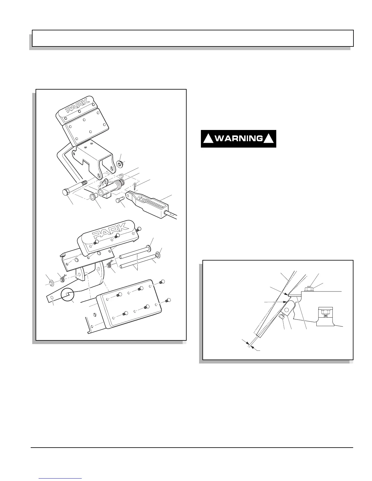
Note the location and orientation of the two torsion
springs (8). Remove the push nut (9) and pin (10) (Ref
Fig. 27 on page K-19) and remove the parking brake
pedal. Some models may use two push nuts on the pin.
Fig. 27 Brake Pedal Removal and Installation
6
7
7
3
2
1
4
5
8
8
9
10
9
Pedal
Latch
No Hole in
Models Prior
to 2001
Older
Models
2001
and
Later
Fig. 28 Catch Bracket and Latch Arm
! !
Cam Must Be Against
Latch Arm At This Point
0.0" Gap
(0.0 mm)
1/4" (6 mm) Max Gap At This Point
1
2
3
4
Pedal Latch Arm
Catch Bracket
.03" (.76 mm) Max Gap
After Adjustment Of Cam
 Loading...


