FRONT SUSPENSION AND STEERING
Page E-7
Repair and Service Manual
Read all of Section B and this section before attempting any procedure. Pay particular attention to all Notes, Cautions and Warnings
Failure of a single spring will result in over-
stressing the other spring; therefore, replace
front springs as a set.
The following procedure will replace one spring at a time.
Loosen front wheels. Lift and support front of vehicle per
SAFETY section. In addition, support front axle with jack
stands. Remove front wheels.
To detach driver side spring:
Fully loosen the two rack and pinion unit lock nuts (15),
one near the bellows and one on the rear side of the rack
and pinion unit, until only one thread is engaged (Ref Fig.
6 on page E-5). Remove the lock nut (15) and washer
(14) from the long bolt (20) and discard lock nut. The
rack and pinion unit is now loose.
Remove the two 1 3/4" long bolts (18) and lock nuts (19)
securing driver side spring to axle and discard lock nuts
(19).
Hold nut (21) with wrench and loosen long bolt (20). Note
location of washer (22) and thread long bolt out as far as
possible to remove the washer, nut and spacer (23).
Then pull long bolt and spring plate (24) from axle and
spring. Retain above items (20 - 24) for assembly at their
original locations.
Pull upper driver side of floor mat out of plastic trim
retainer and away from floor. Locate and remove hard-
ware (25 - 27) securing rear of spring (17) to vehicle
frame and discard lock nuts (27).
To prevent stress and possible damage
to the rack and pinion unit, the driver
side spring must be mounted to the axle with the hardware (20 -
23) installed in its original location (Ref Fig. 6 on page E-5).
Driver side spring installation is the reverse order of dis-
assembly making sure to install the long bolt (20), spring
plate (24), spacer (23), nut (21) and washer (22) in their
original locations. Use new lock nuts (15, 19, 27) to
secure the rack and pinion unit (16), two short bolts (18)
and rear bolts (25).
To detach passenger side spring:
Remove the hardware (18, 19, 24, 28) securing the front
of the passenger side leaf spring (17) to the axle (3) and
discard lock nuts (19) (Ref Fig. 6 on page E-5).
Pull upper passenger side of floor mat out of plastic trim
retainer and away from floor. Locate and remove hard-
ware (25 - 27) securing rear of spring (17) to vehicle
frame and discard lock nuts (27).
Using new lock nuts (19, 27), install passenger side
spring in the reverse order of disassembly.
After the springs are replaced, the axle will
need to be aligned to the frame. Unless the
axle has been replaced, wheel alignment will not be affected;
however, it is always good practice to check wheel alignment
any time the front-end components are replaced or adjusted.
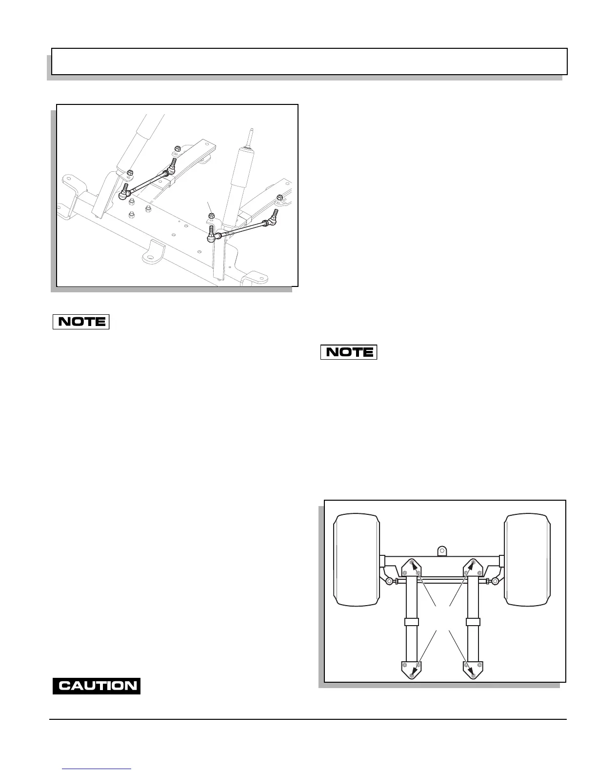
When front springs are replaced, the front axle must be
aligned to the frame. The distance from the center bolt at
rear of left spring to the center bolt at front of right spring
must be the same as the distance from the center bolt at
rear of right spring to the center bolt at front of left spring
(Ref Fig. 8 on page E-7). Tighten the spring hardware
(21, 19, 27) first and rack and pinion unit hardware (15)
next to 35 - 50 ft. lbs. (50 - 70 Nm) torque.
Fig. 7 Axle Linkage Rod Replacement
Ball Joint Nut
Fig. 8 Front Axle Alignment
View from Underside
of Vehicle
Equal
Distance
 Loading...


