EC5000
- 48 - - 49 -
Description of Functional Parameter
5
EC5000
Description of Functional Parameter
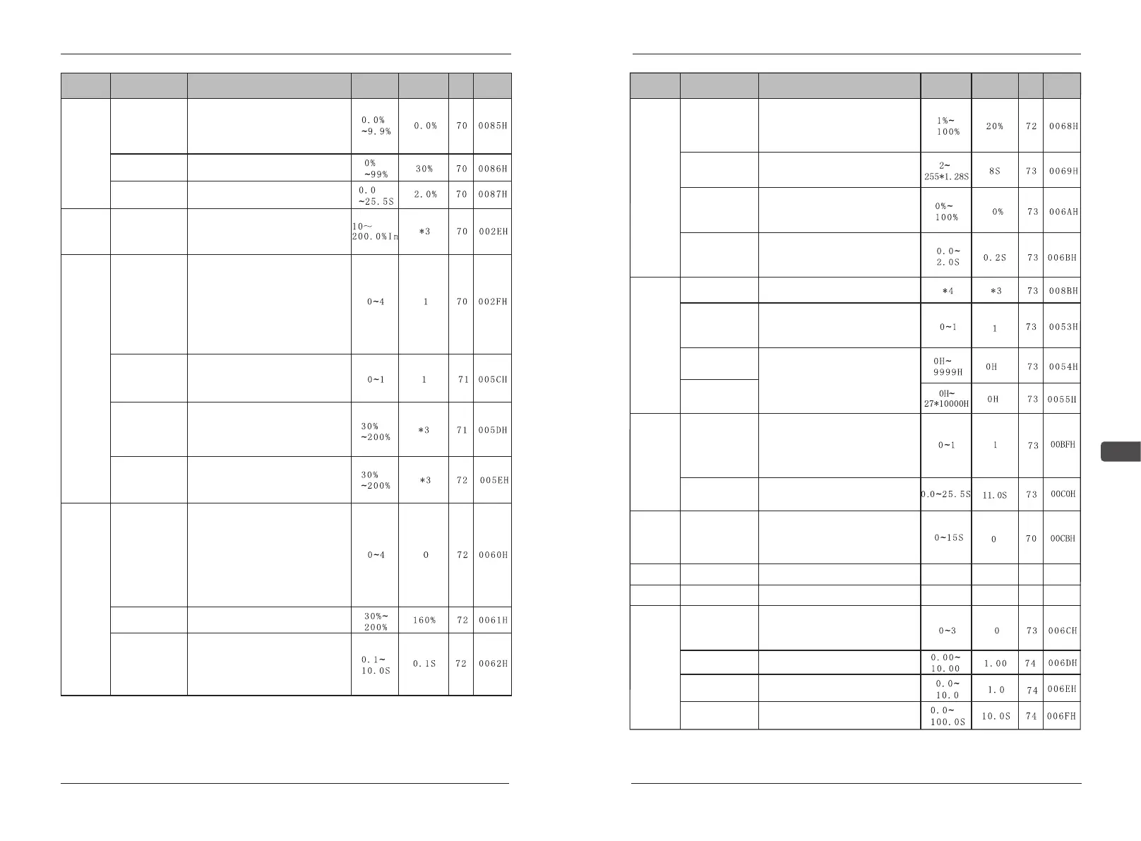
Function
Parameters
Name
Description
Setting
range
Default
Page
Address
C15 Slip
compensation
gain
Rotation difference compensation is
increasing AC drive output
frequency by propotion of motor
loading capacity moment of force to
decrease motor speed difference.
Slip
correction
C16 Motor
no-load current
Motor no-load current
C17 Motor
no-load current
Slip compensation primary delay
time constant
Electronic
thermal
protector
C18 Motor rated
current
Set rated current value for motor
data plate, take the electronic
overheat protector as motor protec-
ting standard current.
C19 Motor
thermal
protection
0: Protection disabled
1: General purpose motor
(time constant 8 min.)
2: General purpose motor
(time constant 5 min.)
3: Blower-cooled motor
(time constant 8 min.)
4: Blower-cooled motor
(time constant 5 min.)
Over
current
stall
preven-
tion
C20 Stall
prevention
during
deceleration
0:without speed loss protection
function during retard
1:with speed loss protection function
during retard
C21 Current
limit/Stall
prevention level
during
acceleration
Unit:1%
AC drive rated curr
C22 Current
limit/Stall
prevention
Level during running
(Stall P Run Level)
Unit:1%
AC drive rated current 100
Output
over
torque
detection
C23 Over torque
detection
0: Detection disabled
1:Over torque detection at speed
agree; continue running after detec-
tion
2: Over torque detection at run;
continue running after detection
3:Over torque detection at speed
agree; coast to stop after detection.
4: Over torque detection at run;
coasts to stop after detection.
C24 Over torque
detection level
100%=inverter rated current
C25 Over-T
torque
If the time of motor current surpa-
ssing torque moment of force
testing standard(C24) is longer than
testing time(C25),over torque
moment of force testing function
works
Function
Parameters
Name
Description
Setting
range
Default
Page
Address
Input/
Output
phase loss
detection
C26 Input phase
loss detection
level SPI
Unit:1%
When setting is 100%,this function
is disabled.DC400V (200V grade)
and DC800V (400Vgrade) to be
100%.
C27 Input phase
loss detection
delay time
C28 Output
phase loss
detection level
SPO
C32 Elapsed
timer L
C33 Elapsed
timer H
Set the input phase missing test
time
Test time=1.28sec×(C27’s value)
Unit:1%
AC drive rated current to be 100%.
C29 Output
phase loss
detection Delay
time
Set output phase missing test time.
AC Drive
elapsed
time
setting
C30 AC Driver
kVA
Read only, display the AC drive
power grade
C31 Elapsed
timer selection
0:total time of accumulative when
AC drive is power on
1:total time of accumulative when
AC drive is running
When C32 is selected to be action
total time, set C32 to be time with
unit of 1 hour and calculate time
from then on.
C34 Frequency
reduction
compensation
When the click in the weak mag-
netic control area, the torque force
is not enough, and frequency redu-
ction compensation needs to be
turned on to increase the torque.
0: OFF 1: ON
Frequency
reduction
compen-
sation
of weak
magnetic
control
area
C35 Frequency
reduction
time
Increase the compensation time of
torque frequency reduction.
C37
C38
Operation
control
C36 Operation
delay time
After the operation signal is given, a
delay function is added. When the
user uses AC drive to power on and
operate directly, the time delay of
0-15s can be set.
Reserved
Reserved
PID
Control
D01 PID Control
0: PID disabled
1: PID enabled
2: PID w/Feed forward
3: PID w/Inverted feedback
D02 Feedback
calibration gain
It’s the gain of PID feedback
detection value for fine adjustment
D03 PID
Proportional gain
Set P control proportion increase.
If set to be 0.0, no P control.
D04 PID
Integral time
Set I control proportion increase.
If set to be 0.00, no I control.