EC5000
- 50 - - 51 -
Description of Functional Parameter
5
EC5000
Description of Functional Parameter
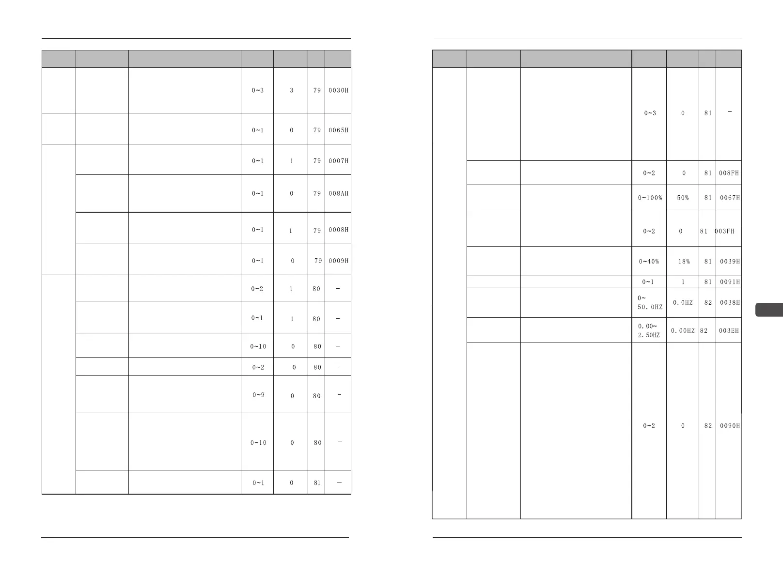
Function
Parameters
Name
Description
Setting
range
Default
Page
Address
F06 Stop
method
selection -OH1-
for inverter
overheat
pre-alarm
0:Ramp to stop-Decel 1(fault)
1:Coast to stop(fault)
2:Ramp to stop-Decel 2 (fault)
3:Continue operation(alarm) at 80%
of frequency reference.
Radiator
overheat
stop mode
F07 DBR
Overheat
0: without braking resistance
overheat protection
1:with braking resistance overheat
protection
Braking
resistance
overheat
protection
F08 Local/
Remote
key function
0:LOCAL/REMOTE key function:
invalid
1:LOCAL/REMOTE key function:
valid
Function
selection
of operator
F09 Local /
Remote
selection
0:When LOCAL/ REMOTE shifting,
re-run is valid when stop order is
inputed
1:When LOCAL/ REMOTE shifting,
re-run is valid at once
F10 Stop key
function
0:STOP key is disabled when
operated from terminals
1:STOP key is always enabled in
any operating mode
F11 Frequency
setting method
from Enter key
0:“ENTER” key not used when set
frequency order with operator
1:“ ENTER” key used when set
frequency order with operator
Auxiliary
function
F12 Monitor
Variable
unit selection
0: m/s
1:Mpa/mm²
2:Kg/ mm²
Pr F12 Pr Set
select
0:Frequency set by key button
number
1:Frequency set by key potentio-
meter adjustment
F13 Operation
panel LCD
brightness
Used to adjust the brightness of
LCD display.
Pr F13 Data
rewrite
0: Data copy 1: Data check
2: Data write
F14 Monitoring
parameter
selection
0: setting frequency
1: output frequence
2: output current 3: output voltage
4: output power 5: voltage EDC
6: feedback PID
Pr F14
Monitoring select
0: setting frequency
1: output frequency 2: output voltage
3: output current 4: output power
5: voltage EDC 6: feedback PID
7: temperature
8: S terminals functional
9: Y terminals functional
10: running time 11: version ROM
F15Operation
panel language
selection
0:Display Chinese
1:Display English
Function
Parameters
Name
Description
Setting
range
Default
Page
Address
Auxiliary
function
Pr F15 LED
Display selection
Only LED manipulator has this
functional code
0: seven items for monitoring:
(Fset、Fout、Vout、Aout、KVA、
EDC、PID)
1:increase two external terminals
S1-8 and Y1-4 for monitoring the
input and the output.
2:increase three items for monito-
ring: TEP、HOU、the VER of
mother board
3:increase five items which monito-
red above 1&2
F16 Low-speed
selection
0:Free running;
1:Running at A16(start freq) ;
2:Running at Zero-speed .
F17 Zero-speed
increase
According to the rating current of
100% set the output current at zero
speed.
F18 Motor tuning
0:no auto tuning;
1:static auto tuning(Suitable for use
in already connected load motor)
2:Dynamic auto tuning(Suitable not
connected to the load of the motor)
F19 Electrical
leakage
With motor set by 100% of the rated
voltage for motor voltage which is
caused by the leakage inductance
of the amount of pressure drop.
F20 AVR
0:No AVR 1:AVR
F21 Brake
frequency
0.00Hz The function is invalid
0.1~50Hz When the stop order is
given, DC injection braking when
deceleration to the set frequency.
F22 UP/DOWN
Step length
0.00Hz Choose the acceleration
time continuous accelerated to the
max frequency.
F23 Wire
selection
This function is enabled when use
terminal operation order.
The default is 0:
Single wire mode: connect S1 is
forward, disconnect S1 is stop.
Second wires mode: connect S1 is
forward, disconnect S1 is stop,
connect S2 is reversal, disconnect
S2 is stop. Three wires mode: S1
rising along the trigger, disconnect
S2 is stop, S3 level switch and
reversing.
The default is 1:
Single wire mode: S1 rising along
the trigger and stop switch Second
wires mode: connect S1 is forward,
disconnect S1 is stop. S2 level
switch and reversing Three wires
mode: S1 rising along the trigger is
forward, disconnect S2 is stop, S3
rising along the trigger is reversal
The default is 2:
Single wire mode: S1 rising along
the trigger and stop switch Second
wires mode: connect S1 is forward,