EC5000
- 56 - - 57 -
Description of Functional Parameter
5
0
1.30
6.0
2.50
12.0
50.00
200.0
50.00
1
1.50
6.0
3.00
12.0
60.00
200.0
60.00
2
1.50
6.0
3.00
12.0
50.00
200.0
60.00
General
purpose
3
1.50
6.0
3.00
12.0
60.00
200.0
72.00
4
1.30
5.0
25.00
35.0
50.00
200.0
50.00
5
1.30
6.0
25.00
50.0
50.00
200.0
50.00
6
1.50
5.0
30.00
35.0
60.00
200.0
60.00
Properties
of
descending
torque
7
1.30
6.0
30.00
50.0
60.00
200.0
60.00
8
1.30
7.0
2.50
15.0
50.00
200.0
50.00
9
1.50
9.0
2.50
20.0
50.00
200.0
50.00
10
1.50
7.0
3.00
15.0
60.00
200.0
60.00
High-
speed
starting
torque
11
1.50
1.5
3.00
20.0
60.00
200.0
60.00
12
1.50
1.5
3.00
12.0
60.00
200.0
90.00
13
1.50
1.5
3.00
12.0
60.00
200.0
120.00
14
1.50
1.5
3.00
12.0
60.00
200.0
180.00
Constant
output
torque
15
1.50
1.5
3.00
12.0
50.00
200.0
50.00
Purpose
Setting
Starting
Frequency
Starting
Voltage
Mid
Frequency
Mid
Voltage
Reference
Frequency
Max
Voltage
Maxi
Frequency
A.motor voltage and frequency property
B.the highest running speed of the motor
Only select high start moment of force on the following circumstance:
(Usually not necessary)
A.long connecting wire(150m or longer)
B.voltage reduce too much during START
C.AC reactor is in AC drive input and output
D.Use motor that power is smaller than AC drive rated output power.
Set motor rated voltage. Calculate fixed V/F mode voltage(A10,A11,A15,A17)
It is 2 times for 400V grade
EC5000
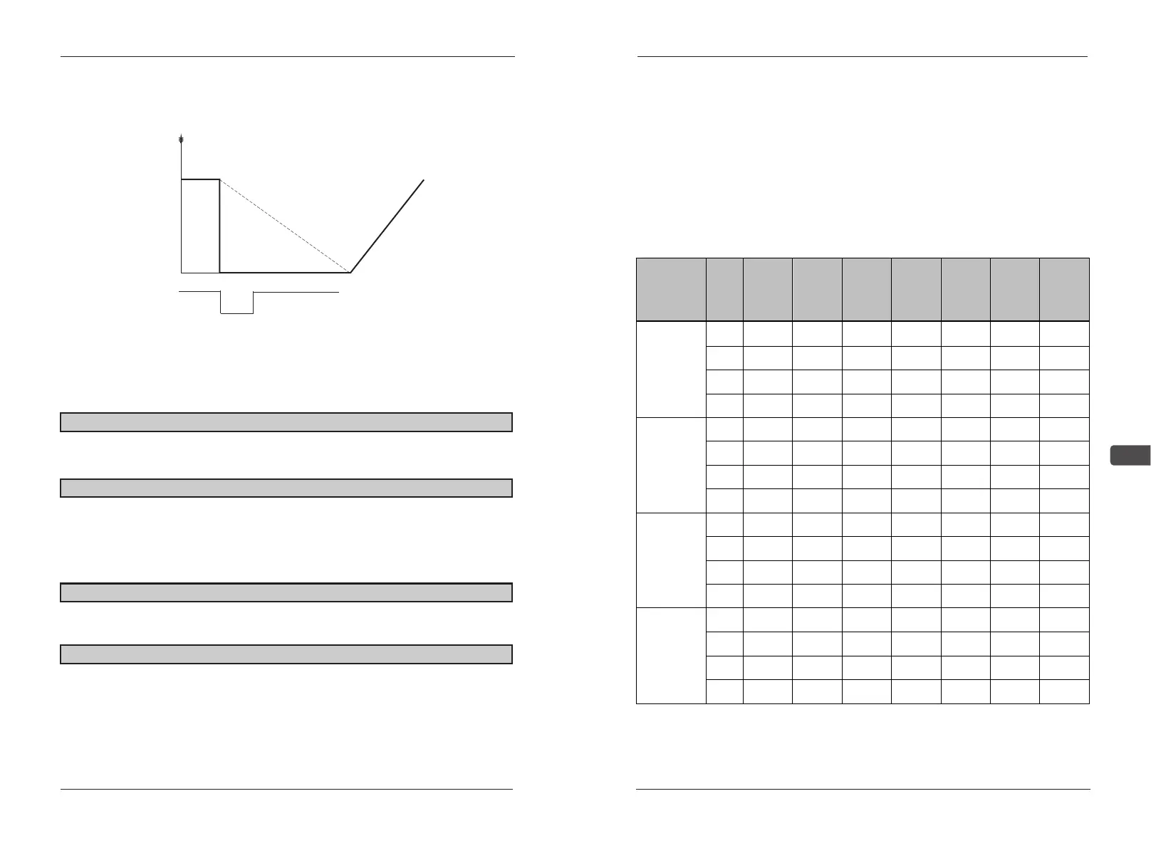
SETTING3: slide to stop with second retard time
Select increase/decrease speed 2(example)
Deliver running order during retard to stop, AC drive will not reaction. AC
drive will start only after retarding time is over. But if retarding times is setting
below Min. BB time (C04),running order during BB time is invalid.
A06 Motor Rotation setting limit: 0~1 factory default:0
0:motor running direction is anti-clockwise with right running order.
1:motor running direction is clockwise with right running order.
A07 Reverse oper setting limit:0~1 factory default:0
0:running in opposite direction is available.
1:running in opposite direction is not available it refuse opposite running
direction order of control circuit terminal or control panel. This setting is suitable
for circumstance that opposition running order will cause error.
A08 Input voltage setting limit:150.0V~255.0V factory default:200.0V
Setting AC drive input voltage. AC drive shift voltage protection according
to this value.
A09 V/F selection setting limit:0~15 factory default:15
0~14:select fixed V/F mode. 15 : select free V/F mode.
The following page shows the fixed V/F mode.(the listed voltge is 200V
grade, for 400V grade, the voltage is 2 times that of 200V)
the following must suitable to select the V/F mode:
deceleration time
Accelerating time
Positive / Reverse Run instruction
Glide
Output frequency
ON
ON
Description of Functional Parameter