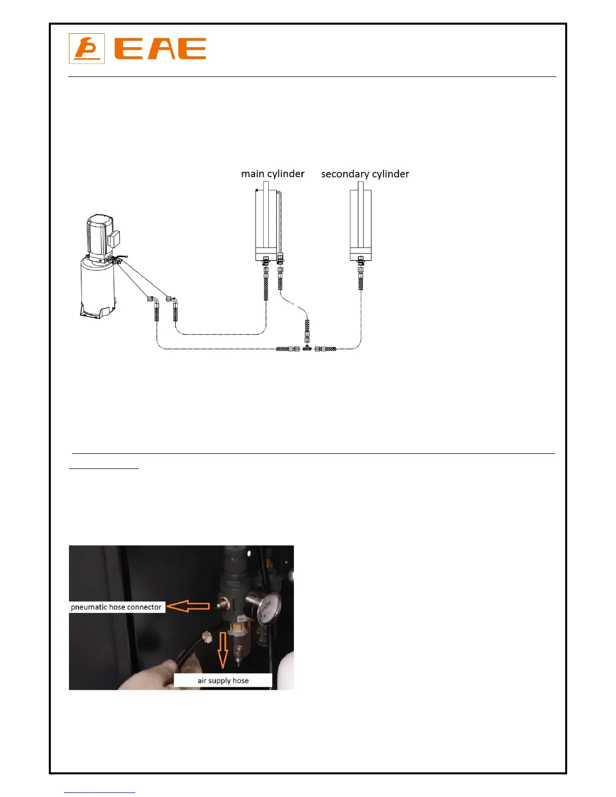
Firstly, connect the oil hoses between the two platforms. There are 3 oil hoses together. And then, connect the 2 oil hoses from the main
platform with the tie-ins remained on the hydraulic block in the control cabinet. Oil hoses go into the cabinet through the holes remained at
the bottom of the cabinet.
Attention: Connect as per the marks on the hoses and do not contaminate the hydraulic components during the connection.
Step 5: Connect the electrical system.
Refer to Annex 1 when fix the electrical system.
Connect the wire connectors for rising and lowering limit switches
Connect the power suppler cable to external electricity supply.
(For three phase power supply, if the lift doesn't raise and the motor may turn in the wrong direction, in such event, interchange wires U, V in
the control cabinet).
Step 6: Connect the pneumatic release system.
Refer to Annex 3.
Screw torque for pneumatic hose connector is 20N*M.
External compressed air shall be prepared by the end user before installation. Pneumatic pressure 6-8 bar.