- 13 -
2.3 Installation
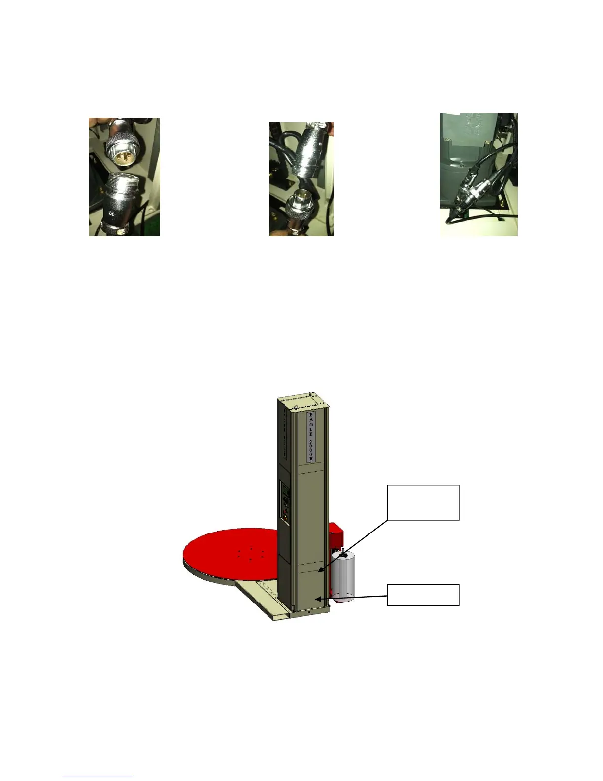
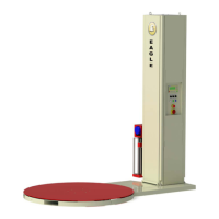
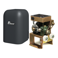
Step 6 - Insert the connector plug inside the bottom of the mast into the corresponding receptacles.
(See Fig 2-9a, 2-9b, 2-9c)
Fig. 2-9a
Fig. 2-9b
Fig. 2-9c
Note: These connectors are for carriage motor power (pre-stretch), photo-electric eye, home
limit switch, and E-Stop switch located on the bottom of the carriage.
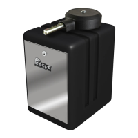
Step 7 - Fasten the lower rear panel into the corresponding position on the post using the pin. (See
Fig. 2-10)
Fig. 2-10
Step 8 - Verify that all screws are tight and then turn on the power. Check to see if the power
indicator is on and that text is displayed on the LCD screen.
Lower Rear
Panel
Pin