Eaton 9395XC UPS 1200kW/1200kVA, 1350kW/1350kVA or 1500kW/1500kVA 164001079—Rev 01 27
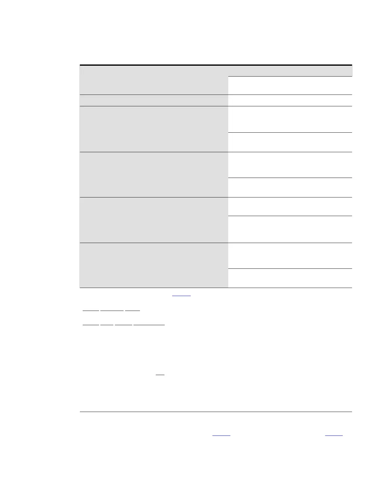
Table 5. 480V Input/Output Ratings and External Wiring Requirements
Basic Unit Rating
Units
Rating 50/60 Hz
kVA
kW
1200
1200
1350
1350
1500
1500
Input and Output Voltage Volts
480/480 480/480 480/480
AC Input to UPS Rectifier (0.99 Minimum pF)
Full load current plus battery recharge current
(3) Phases, (1) Ground
A
Amps
1786 2009 2232
Minimum Conductor Size
Number per Phase
AWG or kcmil
(each)
500
(8)
500
(9)
500
(9)
AC Input to UPS Bypass
Full Load Current
(3) Phases, (1) Ground
B
Amps
1443 1624 1804
Minimum Conductor Size
Number per Phase
AWG or kcmil
(each)
500
(6)
400
(8)
500
(8)
DC Input from Battery Disconnect to UPS
(1) Positive, (1) Negative
C
Total Amps
2657 2989 3322
Minimum Conductor Size
Number per Phase
(1) Positive, (1) Negative
AWG or kcmil
(each)
500
(9)
300
(12)
500
(12)
AC Output to Critical Load
Full Load Current
(3) Phases, (1) Ground
D
Amps
1443 1624 1804
Minimum Conductor Size
Number per Pole
AWG or kcmil
(each)
500
(6)
500
(8)
500
(8)
NOTE Callout letters A, B, C, and D map to Figure 49.
NOTE Bypass wiring data is not applicable to IOM configurations.
Battery Conductor Sizing: Eaton strongly recommends using the specified DC conductor size and quantity shown above for
optimum system performance and battery run time.
Battery Cable Routing Requirements
Conduit applications:
* Each conduit must have a Positive, Negative, and Ground conductor.
* There must be an equal number of positive and negative conductors in a single conduit. Only one ground conductor is required in
each conduit.
NOTE If a 4-pole Automatic Transfer Switch (ATS) is used to connect the UPS to a generator or alternative input source, it may
interrupt the UPS input neutral during its transition between sources. For the 9395XC UPS:
The ATS transition must be open in both directions. The "break" time for the contacts must be at least 50 ms. This allows the UPS
to operate properly, however it is important to evaluate whether the critical load will function properly as its neutral reference is
rapidly (50 ms) switched. Note also that if the UPS load is on bypass, an ATS switchover with interruption of the neutral, will
interrupt the return current path and cause a loss of all phase-to-neutral loads.
If an overlapping neutral or make-before-break ATS switch is used, the neutrals must overlap for a minimum of 50 ms during the
transition.
Terminals E1A through E5A and E9A through E11A are bolted-type terminals. The intercabinet power wiring
connections for this equipment are rated at 90°C. See Table 6 for Internal power cable terminations, Table 9 for
UPS Installation Plan and Unpacking

 Loading...


