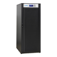
Eaton 93E UPS (15-80 kVA, 380/400/415V) Installation and Operation Manual v
List of Figures
Figure 1-1. Eaton 93E UPS (15–80 kVA) .............................................................. 1-1
Figure 3-1. UPS Cabinet Dimensions (93E 15-20 kVA Front and Right Side Views) .............................. 3-5
Figure 3-2. UPS Cabinet Dimensions (93E 30 kVA Front and Right Side Views) ................................ 3-6
Figure 3-3. UPS Cabinet Dimensions (93E 40 kVA Front and Right Side Views) ................................ 3-7
Figure 3-4. UPS Cabinet Dimensions (93E 60-80 kVA Front and Right Side Views) .............................. 3-8
Figure 3-5. UPS Cabinet Dimensions (Top and Bottom Views) ............................................. 3-9
Figure 3-6. UPS Cabinet Centre of Gravity (93E 15-20 kVA) ............................................... 3-10
Figure 3-7. UPS Cabinet Centre of Gravity (93E 30 kVA) .................................................. 3-11
Figure 3-8. UPS Cabinet Centre of Gravity (93E 40 kVA) .................................................. 3-12
Figure 3-9. UPS Cabinet Centre of Gravity (93E 60 kVA) .................................................. 3-13
Figure 3-10. UPS Cabinet Centre of Gravity (93E 80 kVA) .................................................. 3-14
Figure 3-11. UPS Cabinet as Shipped on Pallet ......................................................... 3-23
Figure 4-1. Removing the Shipping Bracket ........................................................... 4-2
Figure 4-2. Attaching the Ramp to the Pallet .......................................................... 4-3
Figure 4-3. Rolling the Cabinet Down the Ramp ........................................................ 4-3
Figure 4-4. Power Terminal Locations 20-40 kVA ....................................................... 4-6
Figure 4-5. Power Terminal Locations 60-80 kVA ....................................................... 4-7
Figure 4-6. Interface Terminal Locations .............................................................. 4-8
Figure 4-7. Interface Terminal Detail (Terminal Cover Removed) ............................................ 4-9
Figure 4-8. Building Alarm Terminal Block Connector Assignments ......................................... 4-9
Figure 4-9. Interface Wiring Access ................................................................. 4-10
Figure 4-10. Pull Chain Terminal Block Connector Assignments ............................................. 4-11
Figure 4-11. Parallel UPS Control Wiring .............................................................. 4-13
Figure 4-12. Parallel UPS system connections .......................................................... 4-13
Figure 4-13. REPO Terminal Block Connector Assignments ................................................ 4-14
Figure 4-14. Normally-Open REPO Switch Wiring ....................................................... 4-15
Figure 4-15. Normally-Closed REPO Switch Wiring ...................................................... 4-16
Figure 5-1. Main Elements of the UPS System ........................................................ 5-1
Figure 5-2. Path of Current Through the UPS in standard Normal Mode ...................................... 5-3
Figure 5-3. Path of Current Through the UPS in Bypass Mode ............................................. 5-4
Figure 5-4. Path of Current Through the UPS in Battery Mode ............................................. 5-5
Figure 5-5. UPS System Oneline (Dual Input) .......................................................... 5-7
Figure 5-6. UPS System Oneline (Single Input) ........................................................ 5-8
Figure 6-1. UPS Controls and Indicators .............................................................. 6-1
Figure 6-2. UPS Switches ......................................................................... 6-2
Figure 6-3. UPS Control Panel ..................................................................... 6-3
Figure 6-4. Parts of the LCD ....................................................................... 6-5
Figure 6-5. Main Menu and Mimic Screen ............................................................ 6-6
Figure 6-6. Typical Initial Setup Screen ............................................................... 6-9
Figure 6-7. Typical System Control Screen ............................................................ 6-10
Figure 7-1. Optional Mini-Slot Cards ................................................................. 7-1
Figure 8-1. Air Filter Location ...................................................................... 8-3

 Loading...