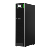
Figure 3: Looking inside the 30/40 kW frame
1. Control panel
2. Door latch
3. Power module (UPM)
4. Internal battery (not included
in the C- model)
5. Communications area
6. Input switch (optional in some
regions)
7. Battery breaker for internal
batteries *
8. Maintenance bypass switch
(optional)
*) In the C-model for external batteries
The system level static bypass in the UPS cabinet determines the attainable
output power of the UPS. The static bypass line consists of a static switch and a
backfeed protection isolation device connected in series. In addition, there is a
system level control unit that constantly monitors the power delivered through the
bypass line or to the input of the UPS. Transfers to static bypass are seamless
and performed automatically by the system as needed, for example, in case of an
extended system overload.
Each UPM includes a rectifier, battery converter, inverter and independent
controls. Each UPM is able to operate and share the load independently, despite
the status of the other UPMs.
In addition, the system can have a UPS-internal maintenance bypass switch as a
factory-installed option.
Table 3: UPS configurations
UPS frame Number of UPMs
Static switch [kW] Internal battery
93PS 20 kW 1 20 Yes
93PS 20 kW C-
model
1 20 No
93PS 40 kW 1 or 2 40 Yes
91PS 15 kW 1 15 Yes
© Eaton Corporation plc 2020. All rights reserved. Revision: 006 Document ID: P-164000493 20 (126)
Eaton 91PS/93PS UPS 8–40 kW User’s and Installation Guide

 Loading...