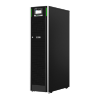
Table 12: 93PS Air conditioning or ventilation requirements during full load
operation
Heat rejection
(BTU/h x 1,000)
Heat rejection
(kW)
Air flow
(l/s)
8 kW 1.17 0.3 70
10 kW 1.46 0.4 70
15 kW 2.19 0.6 70
20 kW 2.92 0.9 100
30 kW 4.38 1.3 140
40 kW 5.84 1.7 200
Table 13: 91PS Air conditioning or ventilation requirements during full load
operation
Heat rejection
(BTU/h x 1,000)
Heat rejection
(kW)
Air flow
(l/s)
8 kW 1.4 0.4 70
10 kW 1.7 0.5 70
15 kW 2.7 0.8 70
20 kW 3.1 0.9 140
30 kW 4.8 1.4 140
Battery locations and enclosures must be ventilated to maintain the hydrogen
concentration below the 4%
vol
safety limit. Adequate air ventilation must be
provided to locations where the UPS and batteries are located. For the 15/20kW
frame with internal batteries, the minimum air flow is 3 m
3
/hour and the minimum
free area of opening for inlet and outlet is 84 cm
2
when natural ventilation is used.
For the 30/40 kW frame with internal batteries, the minimum air flow is 6 m
3
/hour
and the minimum free area of opening for inlet and outlet is 168 cm
2
when natural
ventilation is used. For larger batteries, the ventilation air flow must be
recalculated.
For the dimensions of the 91PS/93PS UPS cabinets, see Figure 9: The
dimensions of the Eaton 91PS/93PS UPS frames.
CAUTION
This product can cause a DC current in the PE conductor. Where a
residual current-operated protective device (RCD) is used for protection
against electrical shock, only an RCD of Type B is allowed on the supply
side of this product.
© Eaton Corporation plc 2020. All rights reserved. Revision: 006 Document ID: P-164000493 41 (126)
Eaton 91PS/93PS UPS 8–40 kW User’s and Installation Guide

 Loading...