Effective July 2010
Instructional Leaflet IL8700C39-04
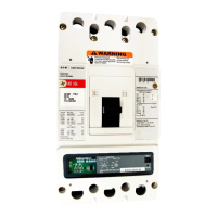
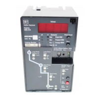
OPTIM OPTIM
DIGITRIP RMS Type 510 610 810 910 750 1050
Instruction Leaflet No. I.L. 29-885 I.L. 29-886 I.L. 29-888 I.L. 29-889 I.L. 29C891 I.L. 29C891
Long Delay Setting X X X X X X
Long Delay Time X X X X X X
Long Time Slope (I2t - I4t) X X
Long Time Memory Powered X X X X X X
Overtemperature X X X X X X
Short Delay Pick-up OPT. OPT. OPT. OPT. X X
Short Delay Time OPT. OPT. OPT. OPT. X X
Flat/I2T Response X X X X X X
Zone Interlocking j j j j j j
Instantaneous Pick-up OPT. OPT. OPT. OPT. X X
DIScriminator Disable s s s s X X
Ground Fault Pick-up OPT. OPT. OPT. OPT. OPT. OPT.
Ground Fault Time OPT. OPT. OPT. OPT. OPT. OPT.
Flat/I2t Response X X X X X X
Ground Time Memory X X X X X X
Zone Interlocking j j j j j j
Ground Fault Alarm Only OPT. OPT.
Interchangeable Rating Plug X X X X X X
Auto Lockout After Trip X X X X X
Mode of Trip LEDs X X X X X X
Battery - for Mode of Trip LEDs X X X X X X
Battery Status LED (Green) X X X X X X
Battery Test Pushbutton X X X X X X
Power/Relay Module X X X X X
Remote Signal Contact
High Load Alarm X X X X X
Long Delay Trip X X X X X
Short Circuit Trip X X X X X
Ground Fault Trip o o o o o
Ground Alarm
Integral Test Provisions X X X X
Trip Unit Status Indication LED X X X X X X
Display Message Test l l
4 Digit Display X X X
IA Current X X X
IB Current X X X
IC Current X X X
IG Ground o o o
Display Stepping Pushbutton X X X
Total Harmonic Distortion [THD] LED X
Per Harmonic X
Waveform Capture m m
4 Digit Display
Phase to Phase [VAB] LED X
Phase to Phase [VBC] LED X
Phase to Phase [VCA] LED X
Protection
Voltage
Metering
Harmonic
Current
Current Metering
(Local and Remote)
Test Remote Signals
Local Trip
Indicators
X = Standard j Use of zone interlocking is optional with breaker wiring modification.
OPT = Optional k Remote location only unless optional AEM local monitor is used.
l Local on face of trip unit. Remote via INCOM/IMPACC to AEM1 or AEM2 or direct to host computer.
m Remote only - direct to host computer via INCOM/IMPACC.
n On AEM denoted by absence of response from addressed breaker.
o Supplied only when trip unit is equipped with ground fault protection option.
p Requires spring release or electrical operator option.
7
EATON CORPORATION www.eaton.com
Table 1 Digitrip Trip Unit Characteristics
 Loading...