< = >@? A/B CDE F/GHI J@KDL M N M L O HPK G@L N HQ R S
T U V W X Y U Z V [ \ Y ]
^_`"ab@c_dfeg"`"hf^ai$e j k l m n m o pq r s t uvwx yz{x |vv}
~
"$ ( +-/////13//1
38
48
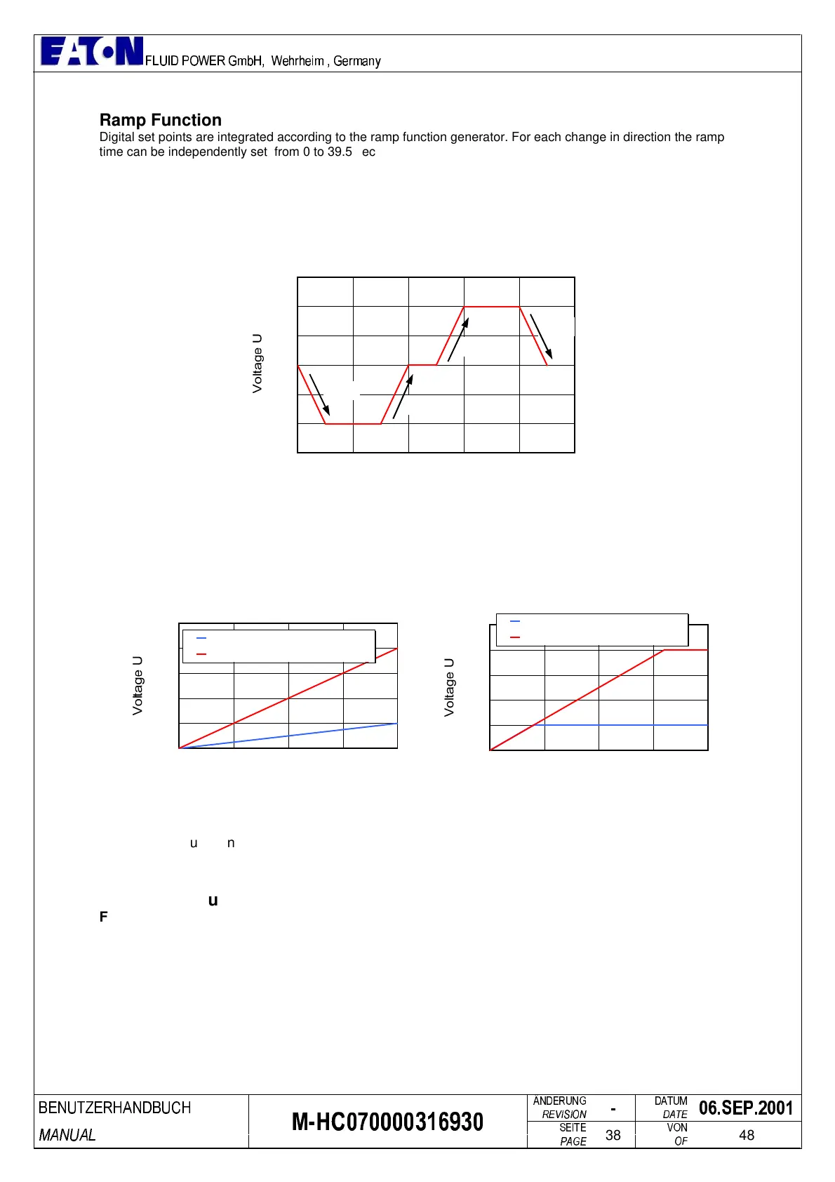
Ramp Function
Digital set points are integrated according to the ramp function generator. For each change in direction the ramp
time can be independently set from 0 to 39.5 sec (0.01 sec resolution).
The ramp characteristics are as follows:
r1.01 0 to negative values
r1.02 negative values to 0
r1.03 0 to positive values
r1.04 positive values to 0
Time t
r1.01
r1.02
r1.03
r1.04
0
+U
-U
Fig. 4: Explanation of Ramp Parameters
E08 = 0 effects only digital set points, constant time base and linear
E08 = 1 effects all set points, constant rise rate and linear
E08 = 2 not used
The ramp function generator can be immediately set to 0 with a “high” signal at the terminal 18 z.
a)
0
2
4
6
8
10
0 1 2 3 4
Time t
S1.01 = 2.00 V, r1.03 = 4.00 s
S1.01 = 8.00 V, r1.03 = 4.00 s
s
V
b)
0
2
4
6
8
10
0 1 2 3 4
Time t
S1.01 = 2.00 V, r1.03 = 4.00 s
S1.01 = 8.00 V, r1.03 = 4.00 s
s
V
Fig. 5: Ramp function: a) E08 = 0, constant time base, b) E08 = 1, constant rise rate
Controller Structure
Fig. 6 shows the complete controller structure for a proportional valve adjustment displacement
control. It also gives information about the definition and mode of action for the controller parameters.
 Loading...


