19
10/09 AWB1230-1605
Effective October 2009
Operation and maintenance of
IZM low voltage air circuit breakers
MOELLER www.moeller.net/de/support
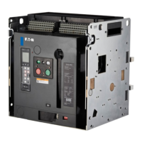
Figure 17. Typical IZM Drawout Circuit Breaker Front Cover
1–Trip Flag (pop-out indicator)
2–Three Accessory Windows
3–Trip Unit
4–Rating Plug
5–Contact Status (open-close)
6–Spring Status (charged-discharged)
7–Manual OFF Button (push)
8–Manual ON Button (push)
9–Manual Charge Handle
10–Optional Operation Counter
11–Padlockable Levering Device Access Door for Drawout Breaker
12–Color-Coded Breaker Position Indicator
13–Nameplate
14–Trip Unit Test Port
15–Trip Unit Cover with Two Mounting Screws (mounting screws will accept customer-supplied lead security meter seals)
1
OPEN
PUSH OFF
DISCHARGED
PUSH ON
CLOSED
CHARGED
CONNECT
TEST
DISCONNECT
CONNECT
TEST
DISCONNECT
5
6
8
7
12
10
11
13
15
14
4
3
2
9
(Red)
(Green)
(Yellow)
(White)
(Red)
(Green)
Red = CONNECT
Yellow = TEST
Green = DISCONNECT

 Loading...