24
Operation and maintenance of
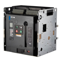
IZM low voltage air circuit breakers
MOELLER www.moeller.net/de/support
10/09 AWB1230-1605
Effective October 2009
Figure 28. Pictorial Diagram of Typical Current Sensing, Processing, and Tripping System
A
B
C
N
G
A
B C
N
01
02 03
Toroidal
Current
Sensor
Rating Plug
Trip Unit
Trip Actuator
Typical IZM Circuit
Breaker
Sensors
ote:N Alternate ground locations may be
required to meet installation requirements.
circuitry and the circuit breaker’s mechanical tripping action can be
verified through the trip unit’s test receptacle (Figure 29). This is
accomplished using a Digitrip Test Kit that provides a secondary
injection test that simulates the current sensors. A small hand-
held IZM functional Test Kit can also be used to check circuitry and
mechanical tripping functions (Figure 30).
When the circuit breaker is shipped from the factory, the trip
unit’s protective functions are normally set at minimum values.
For specific overload tripping characteristics and time/current
curves to coordinate with a load or system, refer to the trip unit
instruction book.
Microprocessor-based trip unit
IZM circuit breakers use any one of a family of DigitripE RMS trip
units whose main features are summarized in Table 4.
Table 4. IZM Digitrip Trip Units
Functions 520Li 520i 520Mi
a
520MCi
a
1150i
a
LSIG protection No Yes Yes Yes Yes
Disable (I) No Yes Yes Yes Yes
GF protection No Yes Yes Yes Yes
GF alarm No No Yes Yes Yes
Display No No Yes
b
Yes
b
Yes
c
Programmable No No No No Yes
Metering No No Yes
Yes
Yes
Power and energy values No No No No Yes
Power quality No No No No Yes
Communication No No No Yes Yes
a
Available control voltages are 24–48 Vdc, and 120 and 240 Vac.
b
One-line, (four characters per line) LCD display.
c
Three-line, (eight characters per line) LED display.
Phase, neutral, ground, and high load current only.
All the electronic trip units are self-powered with regard to their
protective functions. Current signal levels and the tripping energy
are derived from the current sensors integrally mounted in the circuit
breaker. Control power is required to operate certain optional display
and metering functions.
A functional local test of a major portion of the trip unit’s electronic

 Loading...


