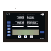
LMR Plus Electric Fire Pump Controllers
July 2011 For more information visit: www.chfire.com PS05805008K/E
Fire Pump Controllers 1-1
Features
Typical Specifications
1. Approvals
A. The Fire Pump Controller shall meet the require-
ments of the latest edition of NFPA 20 and shall be
listed by [Underwriters Laboratories (UL)]and ap-
proved by [Factory Mutual Research (FM)] [Cana-
dian Standards Association (CSA)] [New York De-
partment of Buildings (NYSB)] and carry the CE
marking for fire pump service.
2. Starting Type
A. The controller shall be of the combined manual and
automatic type designed for [Full Voltage Starting]
[Part Winding Starting] [Primary Resistor Starting]
[Autotransformer Starting] [Wye-Delta (Star-Delta)
Open Transition Starting] [Wye-Delta (Star-Delta)
Closed Transition Starting] [Solid State Soft Start
Starting]
3. Ratings
A. The Controller shall have a withstand rating of
100,000 RMS symmetrical amperes @ [208V] [240V]
[380V] [400V] [415V] [480V] [25,000 @ 600VAC].
4. Construction
A. The controller shall include a motor rated combina-
tion isolating switch and circuit breaker, mechanically
interlocked and operated with a single externally
mounted handle.
B. The isolating switch shall be rated to disconnect the
motor load.
C. The isolating switch/circuit breaker combination shall
be mechanically interlocked such that the enclosure
door cannot be opened when the handle is in the on
position except by a tool operated defeater mechan-
ism.
D. The controller manufacturer shall manufacture the
contactor, isolating switch, circuit breaker, pushbut-
tons, and enclosures. Brand-labeled components
will not be accepted.
5. Enclosure
A. The controller shall be housed in a NEMA Type 2
(IEC IP11) drip-proof, powder baked finish, frees-
tanding enclosure.
B. Optional Enclosures:
1. NEMA 3R (IEC IP14) rain-tight enclosure.
2. NEMA 4 (IEC IP66) watertight enclosure.
3. NEMA 4X (IEC IP66) watertight 304 stainless
steel enclosure.
4. NEMA 4X (IEC IP66) watertight 316 stainless
steel enclosure.
5. NEMA 4X (IEC IP66) watertight corrosion resis-
tant enclosure.
6. NEMA 12 (IEC IP52) dust-tight enclosure.
6. Microprocessor Control
A. The controller shall come complete with a 4 line by
40 character LCD display mounted on a panel open-
ing in the front door. The LCD display shall indicate
the following:
1. Main screen displaying system pressure, three-
phase voltage and amperage readings, system
frequency, date, and time.
2. Set point review screen displaying the pro-
grammed pressure start and stop points, and
weekly test time.
3. Controller statistics screen, including:
a. Powered Time
b. Motor Run Time
c. Number of Calls to Start
d. Number of Starts
e. Last Motor Start Time
f. Last Motor Run Time
g. Last Low Pressure Start
h. Minimum System Voltage
i. Maximum System Voltage
j. Minimum System Frequency
k. Maximum System Frequency
l. Minimum System Pressure
m. Maximum System Pressure
n. Last System Startup
o. Last Phase Failure
p. Last Phase Reversal
q. Last Locked Rotor Trip
r. Maximum Run Current
s. Last Locked Rotor Current
4. Controller diagnostics screen, including:
a. Date & Time
b. Firmware Version
c. Shop Order Number
d. Customer Order Number
e. Transformer Output Voltage
f. Current Transformer Outputs
g. Pressure Transducer Calibrated Settings
h. Input Status
i. Output Status
5.
Display last messages screen that will display
up to 10,000 alarms/messages stored in the
controllers' memory.
6. Display up to ten (10) custom messages of up to
100 characters each, which will continually scroll
across the fourth line of the display.
7. Remaining time left on active timers.
B. The controller shall be supplied with ten (10) green
status LED’s for the following:
1. Power On
2. Pump Running
3. Local Start
4. Remote Start
5. Deluge Valve
6. Emergency Start

 Loading...