LMR PLUS Electric Fire Pump Controllers with Transfer Switch
Features
1 - 3
For more information visit: www.ch re.com
January 2012
FT80 Reduced Voltage - Wye Delta (Star_Delta) Closed
BR05805063K/K
The LMR Plus Electric Fire Pump Controllers meet or exceed the requirements of Under-
writers Laboratories, Underwriters Laboratories Canada, Factory Mutual, the Canadian
Standards Association, New York City building code, CE mark and U.B.C / C.B.C. Seis-
mic requirements, and are built to NFPA 20 standards.
Standards & Certifi cation
Product Features
Programming Menu
General
The LMR Plus programming menu is
divided into 8 different sub-menus. Each
sub-menu contains information relative to
it’s particular function. A brief description
of each sub-menu is listed below.
Language
The language sub-menu allows the user
to select English, French or Spanish or
Other languages to be viewed on the LCD
Display. Several other languages can be
uploaded into the controller. Contact the
factory for details.
Regional
Regional settings include the ability to
program the date by adjusting the Month,
Day, Year and Day of Week. As well, the
Current Time can be adjusted on the 24
hour clock.
Pressure
A variety of pressure settings can be
programmed in the pressure sub-menu.
These settings include disabling the
pressure transducer; setting of the start
point, stop point, low pressure alarm, high
pressure alarm, stop mode, proof pres-
sure switch (for foam units), low suction
shutdown (low foam shutdown), pressure
deviation and hourly pressure recording.
Refer to the LMR Plus operation manual
IM05805020K for details.
Timers
Timers in the LMR Plus that can be
programmed include: Run Period Timer
(RPT), RPT Start Mode, Acceleration Timer
(AT), Weekly Test Timer, Fail to Start
Timer (FST) and Sequential Start Timer
(SST). Refer to the LMR Plus operation
manual IM05805020K for details.
Alarm Set Points
There are fi ve settable alarm points that
can be programmed by the user. They in-
clude: Phase Rotation, Over Voltage (OV),
Under Voltage (UV), Over Frequency (OF)
and Under Frequency (UF). Refer to the
LMR Plus operation manual IM05805020K
for details.
Custom Inputs / Outputs
There is provision on the Power I/O Board
to accept up to 9 additional inputs and
9 additional outputs. The inputs can be
labeled using one of 11 pre-set input
descriptions or assigned a custom descrip-
tion that is programmed by the user. The
optional outputs can be programmed to
indicate up to 25 output conditions. As
well, two optional alarm LED’s can be pro-
grammed for up to 12 alarm conditions.
All optional inputs, outputs and LED’s can
be linked, as required.
Inputs can be programmed to energize
the common alarm output, link to relays
and optional LED’s and latch until reset
by the user. Outputs can be programmed
for fail safe and latch until reset by the
user. Optional inputs and outputs can be
programmed with time delay functions.
USB External Drive
General
When using an external USB Drive, the
drive should conform to the following
minimum specifi cations:
Min: 128mb
Max: 2 Gig
FAT16 protocol
USB 1.0 or 2.0
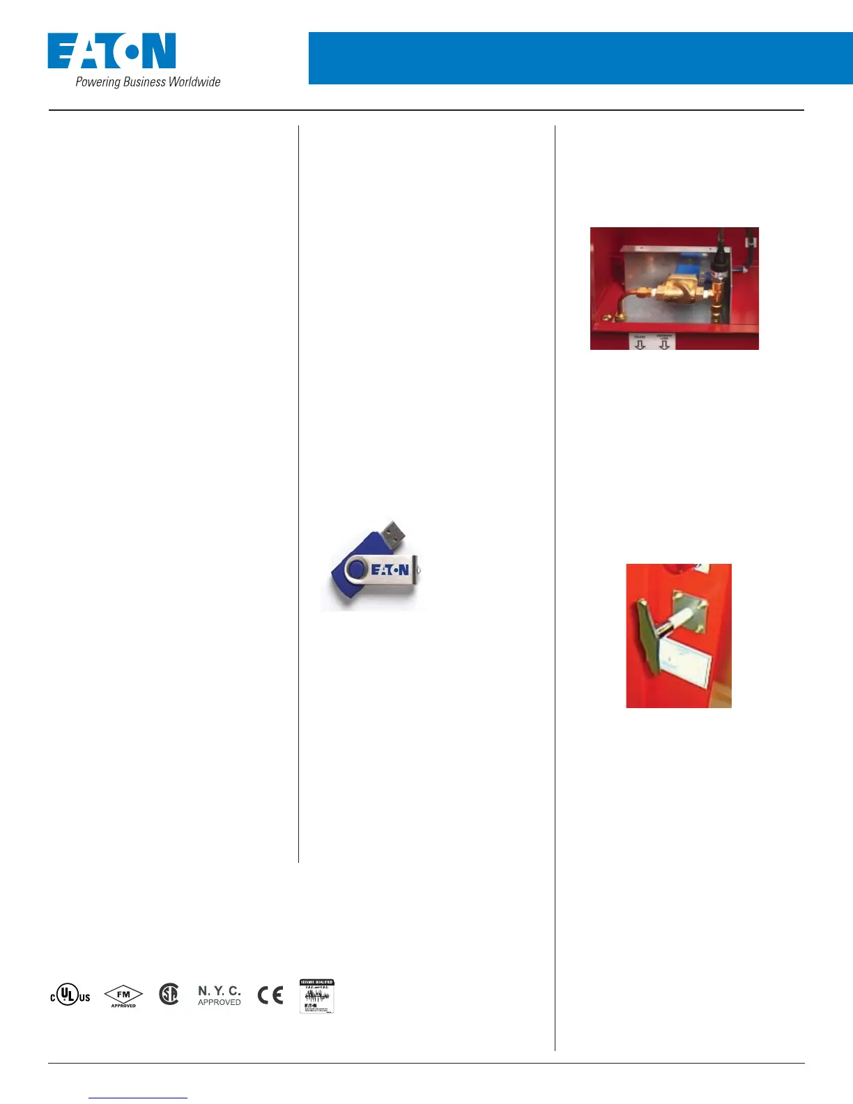
Drain Valve Solenoid
All LMR Plus electric controllers are
equipped with a drain valve solenoid used
for weekly test purposes.
NEMA 2 Enclosures
All LMR Plus controllers come standard
with NEMA 2 enclosures unless otherwise
ordered. Available options include: NEMA
3R, 4, 4X, 12.
Emergency Start Operator
A mechanically operated emergency start
handle activates the motor contactor inde-
pendent of any electrical control circuits or
pressure switch input.