8
Instruction Leaet PUB53675
Effective December 2021
PowerXL DM1 and DM1 Pro series VFD
EATON www.eaton.com
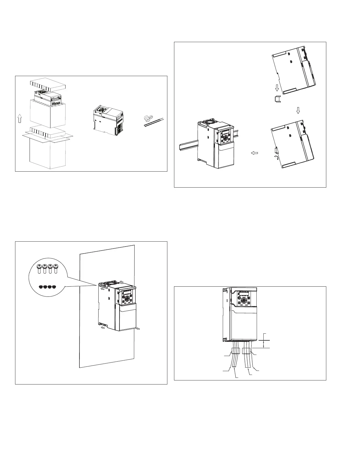
FR2 mounting instructions
Step 1.
Lift the drive out from the carton, remove the packaging. The
magnetic cores and cable ties are only included in EMI version drive.
Step 2.
Screw mounting: Attach the drive to the mounting plate with four
M5X20 (or 3/16 in.) screws and four M5 (or 3/16 in.) nuts. The
opening dimension on the mounting plate should follow required
dimension (refer to the dimension drawing in the instruction leaflet).
DIN Rail mounting: Lift the drive at an angle about 30 degrees.
Align the top hooks of drive DIN rail mounting slot with DIN rail top
edge. Push down and rotate the drive to clip the bottom hooks on
the bottom DIN rail edge.
+
Screw mounting
Four M5x20 or 3/16 inch screws
Four M5 or 3/16 inch nuts
Torque: 3 N.m (26.6 lb/in.)
Step 3. (EMI version only):
The input wires (including 3 line wires and 1 input grounding wire)
should run through the input magnetic core before connecting to
input terminal block and grounding hole. Use a cable tie to tie the
input magnetic cores to the input wires. The output wires (only 3
motor wires) should run through the output magnetic core before
connecting to output terminal block.
The output grounding wire should not run through the output
magnetic core. Use a cable tie to tie the output magnetic cores to
the output wires. The maximum distance between input / output
magnetic cores top surface and drive bottom surface is 100 mm
(3.94 in.). The height of input magnetic core is bigger than output
magnetic core for 3 phase FR2 EMI version, but they are the same
for 1 phase FR2 EMI version.
DIN Rail mounting
3 line wires
Input grounding wire
Output grounding wire
Max. distance: 100 mm (3.94 in.)
3 motor wires
Input magnetic core
Output magnetic core

 Loading...


