Instruction Leaflet IL0102002E
Effective April 2018
Ring Main Unit Operation Instruction
17EATON CORPORATION www.eaton.com
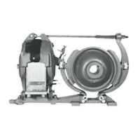
Figure 13 Grounding position diagram
3. RMU fixation
3.1. The bottom of the switchgear is linked to the metal base
frame with bolts, enabling the switchgear to be fixed on the
frame (the cabinet shall have 4 connection joint surfaces with
the frame). Use M20 connecting screws and bolts, with the
torque of 40 + 4 Nm.
4. RMU grounding
The grounding bar of the RMU must be connected to the
grounding grid of the site. The grounding position of the RMU is
inside the right side frame of the cabinet chassis. See Figure 13.
Use M12 connecting screws or bolts, with the torque of 70
±7Nm. The grounding wire is not included in the supply scope.
3.2. Check all the fastening bolts for looseness, and all the wirings
for reliability.
3.3. Check whether the 3-position load switch mechanism can be
operated flexibly, whether the load switch can open and close
freely; check for any abnormity. Check whether the interlocks
are reliable.
WARNING
THE CHARGING DEVICE SHALL NOT BE IN CHARGING STATE DURING
THE INSTALLATION AND CONNECTION OF THE RMU. OTHERWISE, THIS
MAY CAUSE PERSONAL INJURY.

 Loading...