Instruction Leaflet IL0102002E
Effective April 2018
Ring Main Unit Operation Instruction
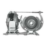
1. Locking plug; 2. Sealed housing; 3. Fuse; 4. Fuse cylinder; 5. Pull handle
20 EATON CORPORATION www.eaton.com
Figure 15 Fuse cylinder structure drawing
Figure 16 Fuse cylinder operation example
6. Fuse installation (equipped with the fuse’s transformer feeder unit)
The fuse shall be installed and replaced by properly trained
professionals.
Before the RMU is put into operation, properly install the chosen
fuse as described in the following procedures:
Open the combination unit branch load switch;
Move the 3-position load switch to the ground position, to
ensure that both ends of the fuse are grounded;
As shown in Figure 16, move the handle from the vertical
place to horizontal place, maintain and withdraw the locking
plug horizontally. Handle with care, to avoid any damage to the
fuse cylinder;
a.
b.
c.
Check the silicone rubber sleeves for any damage, and the
contact button on the locking plug for any permanent
deformation;
Install a new fuse, ensuring a dimension of 2 to 4mm as shown
in Figure 17. Check whether the installation direction is correct,
because the fuse’s striker pushes the load switch to open after
the fuse is blown. Therefore, the striking end of the fuse (small
end) must be outward;
d.
e.
Pull up the handle
to replace the fuse

 Loading...