Instruction Leaflet IL0102002E
Effective April 2018
Ring Main Unit Operation Instruction
28 EATON CORPORATION www.eaton.com
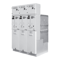
4. RVAC cabinet types
RVAC series Primary scheme Type No.
Name
Function Others
RVAC-B(A) Cable incoming
cabinet
RVAC-K
RVAC-T
RVAC-L
The incoming/outgoing cable is
connected directly to the bus, with
a metal stainless steel protection
case. The voltage display is
offered, for the connection of
incoming/outgoing cable.
1. The HV part is inside the SF6 gas.
2. Expandable to the left and right or
bushings can be added
3. Termination head (for end cabinet)
4. Equipped with voltage presence display
5. Cabinet A is air insulated, while Cabinet B
is SF6 gas insulated
Cable outgoing
cabinet
Equipped with a three-position
load switch, to connect or break
the connection of
incoming/outgoing cable with the
bus, enabling simultaneous
grounding of the three phases of
the incoming/outgoing cable,
offering short circuit making
capacity, for the control of the
incoming/outgoing cable
1. Expandable on both sides
2. Cable incoming/outgoing is available on
the side
3. Manual/electric operating mechanism
4. Equipped with voltage presence display
and fault indicator
5. Ground switch interlocking device
Combination unit
cabinet
Equipped with the same load
switch as the incoming/outgoing
cabinet, and connected in series
with the fuse of high breaking
capacity to constitute a
combination unit, to control, open
and close, and isolate the
transformer and its distribution
circuit, and protect against short
circuit current and overload current
at the high voltage side of the
transformer, the transformer and
the low voltage distribution circuit.
1. For transformer protection(fuse protection)
to the use of 1250 kVA transformer
2. Transfer current 1500A
3. Expandable on both sides
4. Both ends of the fuse are grounded during
side incoming maintenance
5. Manual/electric operating mechanism
6. Equipped with voltage presence display
and ground interlocking device
7. Optional relay protection and trip unit, for
improving the performance of the fuse
when breaking at small currents.
8. Optional thermal switch start tripping
device to provide the transformer with
Bus coupling
cabinet
Equipped with a two-position load
switch, with load connecting or
breaking main bus option for bus
coupling.
1. Main bus is not grounded
2. Rising cabinet is not needed
3. Incoming cabinet can be interlocked with
4. Key locks can be supplied
 Loading...
