Instruction Leaflet IL0102002E
Effective April 2018
Ring Main Unit Operation Instruction
Press down the
handle to install the
fuse
21EATON CORPORATION www.eaton.com
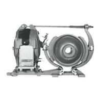
Figure 17 Fuse cylinder structure diagram
Figure 18 Fuse cylinder operation example
Before inserting the fuse into the insulation cylinder, clear and
clean the silicon rubber surface with alcohol cotton paper. Then
apply silicon grease evenly on the surface of the silicon rubber
special grease smearing
As shown in Figure 18, insert the fuse into the insulation
cylinder horizontally, ensuring the inner side of the fuse has
good contact with the contact button inside the insulation
cylinder. Push the locking plug slightly to make the handle’s
notch clutch onto the pin of the cabinet. Then press the handle
from the horizontal position to vertical position, to complete the
installation of the fuse.
f.
g.
During operation, the fuse must be replaced after blown out. Be
careful and cautious during the replacement of the fuse. For the
consideration of safety, wait at least for 10 minutes after the
action of the fuse, the circuit is isolated by the load switch, the
ground switch is closed, and both ends of the fuse are grounded.
Then replace the fuse as follows:
Make sure that the fuse has blown out, and the load switch has
opened;
Move the 3-posiition load switch to the ground position,
ensuring that both ends of the fuse are grounded;
a.
b.
1. Locking plug; 2. Sealed enclosure; 3. Fue; 4. Fuse cylinder; 5. Pull handle

 Loading...