EasyManua.ls Logo

EAW KF300i User Manual

EAW KF300i
48 pages
To Next Page IconTo Next Page
Page #1 background imageLoading...
Page #1 background image
A
C
O
U
S
T
I
C
A
L
P
E
R
F
O
R
M
A
N
C
E
P
A
R
T
N
E
R
S
H
I
P
APP TECH DATA
VOLUME ONE
EASTERN ACOUSTIC WORKS, INC. One Main Street, Whitinsville, MA 01588 • TEL: (508) - 234 - 6158 • FAX: (508) - 234 -
8251
Volume I: Release 1.1 APP Page 17
3.0 KF300
I
VA
®
SYSTEM
3.1 KF300I ARCHITECTURAL SPECIFICATIONS
The three-way full range loudspeaker system shall incorporate a 12-inch low frequency transducer, a
170 mm (nominal 7-inch) cone mid frequency transducer and a high frequency compression driver
mounted to a constant horizontal coverage horn. The total system shall meet the following perfor-
mance criteria: Frequency Response of 65 Hz - 18k Hz ±3 dB; Axial Sensitivity (1 W @ 1 m) of 101 dB
SPL (LF), 106 dB SPL (MF & HF); 100 hour sine wave Power Handling of 250 Watts (65 Hz to 300
Hz), 100 Watts (300 Hz to 18 kHz); Horizontal coverage of 90° between -6 dB points; Vertical cover-
age of 50° between -6 dB points.
The system’s low frequency driver shall be loaded into a bi-tuned vented box that provides optimally
controlled acoustic diaphragm loading. The mid frequency driver shall have a carbon fiber cone and
be loaded into a constant horizontal coverage horn constructed of 3 mm cross-grain-laminated birch
hardwood. The horn flare shall be reinforced with high density polyurethane foam and shall incorpo-
rate a center displacement plug. The high frequency driver shall utilize a titanium diaphragm not less
than 44 mm in diameter. An internal passive frequency dividing network shall provide a fourth order
acoustic crossover between the mid and high frequency subsystems and shall incorporate system
equalization.
The enclosure shall be a trapezoidal cabinet constructed of void-free cross-grain-laminated birch
plywood with internal bracing. It shall be finished in a black catalyzed polyurethane coating. The
front of the system shall be covered with a protective perforated steel grill assembly, coated with
vinyl to dampen resonance and backed with acoustically transparent open cell foam to reduce the
ingress of dust into the system. Hanging fixture attachment points shall be installed in the top and
bottom of the enclosure and mating clips shall be included with the system. Cabinet sides shall be
tapered in such a way as to simplify construction of arrays.
The three-way full range loudspeaker system shall be the EAW model KF300i.
Question and Answer IconNeed help?

Do you have a question about the EAW KF300i and is the answer not in the manual?

EAW KF300i Specifications

General IconGeneral
Configuration2-way
Operating ModePassive
Enclosure MaterialPlywood
Nominal Impedance8 ohms
Crossover Frequency1.8 kHz
HF Subsystem1 x 1.4" compression driver
Coverage Pattern90° x 50°
TypeFull-range speaker
Sensitivity99 dB
ConnectorsNeutrik NL4
LF Subsystem12-in woofer
LF Driver12-in woofer
HF Driver1.4" compression driver

Summary

3.0 KF300i VA® SYSTEM

3.1 KF300i ARCHITECTURAL SPECIFICATIONS

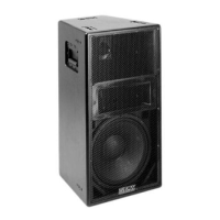
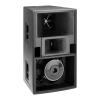
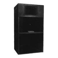
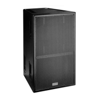
Details the architectural specifications for the KF300i loudspeaker system.

3.2 MECHANICAL DRAWINGS

3.2.1 KF300iP & KF300ixP INSTALLATION CONFIGURATION

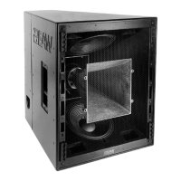
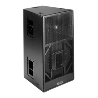
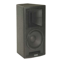
Provides installation configuration details and dimensions for KF300iP and KF300ixP models.

3.2.2 KF300iR & KF300ixR PORTABLE CONFIGURATION

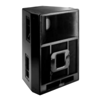
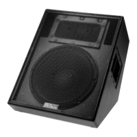
Details installation configuration and dimensions for KF300iR and KF300ixR portable models.

3.3 INPUT PANEL

3.3.1 KF300iP INSTALLATION CONFIGURATION

Diagram and specifications for the KF300iP input panel, including connector types.

3.3.2 KF300iXP INSTALLATION CONFIGURATION

Details the input panel configuration for the KF300iXP, noting bi-amplification mode.

3.3.3 KF300iR PORTABLE CONFIGURATION

Shows the input panel configuration for the KF300iR portable model with Neutrik connectors.

3.3.4 KF300iXR PORTABLE CONFIGURATION

Details the input panel configuration for the KF300iXR portable model, including connector details.

3.4 HANGING HARDWARE

3.4.1 2" x 2" STEEL L-PLATE

Diagram and specifications for the 2" x 2" steel L-plate hanging hardware.

3.4.2 CLIP HARDWARE

Illustrates the clip hardware used for hanging the loudspeaker system.

3.4.3 AMFDS-KF300/SB330RV-T TRUSS

Diagrams and dimensions for the AMFDS-KF300/SB330RV-T truss system.

3.4.4 AMFDS-KF300-T TRUSS

Shows diagrams and dimensions for the AMFDS-KF300-T truss system.

3.4.5 TYPICAL HANGING CONFIGURATIONS

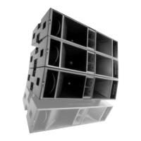
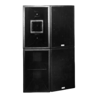
Information on typical hanging configurations for the system.

3.4.6 TYPICAL INSTALLATION CONFIGURATIONS

Details typical installation configurations for the loudspeaker system.

3.5 KF300i POLAR RESPONSE

3.5.1 HORIZONTAL POLAR DATA

Presents horizontal polar response data for the KF300i system.

3.5.1.1 OCTAVE BAND 125Hz

Horizontal polar response data for the KF300i in the 125 Hz octave band.

3.5.1.2 OCTAVE BAND 250Hz

Horizontal polar response data for the KF300i in the 250 Hz octave band.

3.5.1.3 OCTAVE BAND 500Hz

Horizontal polar response data for the KF300i in the 500 Hz octave band.

3.5.1.4 OCTAVE BAND 1,000Hz

Horizontal polar response data for the KF300i in the 1000 Hz octave band.

3.5.1.5 OCTAVE BAND 2,000Hz

Horizontal polar response data for the KF300i in the 2000 Hz octave band.

3.5.1.6 OCTAVE BAND 4,000Hz

Horizontal polar response data for the KF300i in the 4000 Hz octave band.

3.5.1.7 OCTAVE BAND 8,000Hz

Horizontal polar response data for the KF300i in the 8000 Hz octave band.

3.5.1.8 OCTAVE BAND 16,000Hz

Horizontal polar response data for the KF300i in the 16000 Hz octave band.

3.5.2 VERTICAL POLAR DATA

Presents vertical polar response data for the KF300i system.

3.5.2.1 OCTAVE BAND 125Hz

Vertical polar response data for the KF300i in the 125 Hz octave band.

3.5.2.2 OCTAVE BAND 250Hz

Vertical polar response data for the KF300i in the 250 Hz octave band.

3.5.2.3 OCTAVE BAND 500Hz

Vertical polar response data for the KF300i in the 500 Hz octave band.

3.5.2.4 OCTAVE BAND 1,000Hz

Vertical polar response data for the KF300i in the 1000 Hz octave band.

3.5.2.5 OCTAVE BAND 2,000Hz

Vertical polar response data for the KF300i in the 2000 Hz octave band.

3.5.2.6 OCTAVE BAND 4,000Hz

Vertical polar response data for the KF300i in the 4000 Hz octave band.

3.5.2.7 OCTAVE BAND 8,000Hz

Vertical polar response data for the KF300i in the 8000 Hz octave band.

3.5.2.8 OCTAVE BAND 16,000Hz

Vertical polar response data for the KF300i in the 16000 Hz octave band.

3.6 KF300i PERFORMANCE DATA

3.6.1 AXIAL FREQUENCY RESPONSE

Presents the axial frequency response of the KF300i system.

3.6.2 OFF AXIS FREQUENCY RESPONSE

Details off-axis frequency response for the KF300i system.

3.6.2.1 HORIZONTAL (NORMALIZED TO AXIAL RESPONSE)

Horizontal off-axis frequency response normalized to axial response.

3.6.2.1 HORIZONTAL (NORMALIZED TO AXIAL RESPONSE) CONTINUED

Continued horizontal off-axis frequency response normalized to axial response.

3.6.2.2 VERTICAL (NORMALIZED TO AXIAL RESPONSE)

Vertical off-axis frequency response normalized to axial response.

3.6.2.2 VERTICAL (NORMALIZED TO AXIAL RESPONSE) CONTINUED

Continued vertical off-axis frequency response normalized to axial response.

3.6.3 KF300i IMPEDANCE

Presents the impedance data for the KF300i loudspeaker.

3.6.4 BEAMWIDTH VS. FREQUENCY

Analyzes beamwidth characteristics of the KF300i across frequencies.

3.6.4.1 GRAPHIC DATA

Graphic representation of beamwidth vs. frequency for the KF300i.

3.6.4.2 TABULAR DATA

Tabular data for beamwidth vs. frequency for the KF300i system.

3.6.5 Q & DIRECTIVITY VS FREQUENCY

Examines Q and directivity index of the KF300i versus frequency.

3.6.5.1 GRAPHIC DATA

Graphic data illustrating Q and directivity index versus frequency for KF300i.

3.6.5.2 TABULAR DATA

Tabular data for Q and directivity index versus frequency for the KF300i.

3.6.6 EFFICIENCY VS FREQUENCY

Presents efficiency data for the KF300i system as a function of frequency.

3.6.7 DISTORTION MEASUREMENTS

Details distortion measurements for the KF300i loudspeaker.

3.6.7.1 THD DATA

Presents Total Harmonic Distortion (THD) data for the KF300i.

3.6.7.2 HARMONIC DISTORTION DATA

Shows harmonic distortion data for the KF300i at different power levels.

3.6.8 ENERGY TIME CURVE MEASUREMENTS

Information on Energy Time Curve measurements for the KF300i system.

3.7 CCEPT™ CROSSOVER & POWERING OPTIONS

3.7.1 MX300-3 CCEPT™

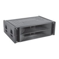
Details the MX300-3 CCEPT crossover and powering options.

3.7.1.1 CONFIGURATION DATA

Provides configuration data for the MX300-3 CCEPT crossover components.

3.7.1.2 RESPONSE DATA

Presents response data curves for the MX300-3 CCEPT system.

3.7.2 MX200-3 CCEPT™

Details the MX200-3 CCEPT crossover and powering options.

3.7.2.1 CONFIGURATION DATA

Provides configuration data for the MX200-3 CCEPT crossover components.

3.7.2.2 RESPONSE DATA

Presents response data curves for the MX200-3 CCEPT system.

3.7.3 KF300i TYPICAL AMPLIFIER CONFIGURATION

Illustrates typical amplifier configurations for the KF300i system.

Related product manuals