Betriebsanleitung · User Guide
22
[ 23. Endlagendämpfung Z1 ]
Funktionsbeschreibung (Bild-4)
Ausgangsposition
• Kolben K ist in Endstellung E2
• Anschluss A1 ist mit Druck
beaufschlagt
• Anschluss B1 ist drucklos
Umschaltung in Schaltstellung 1
• Anschluss B1 wird mit Druck
beaufschlagt
• Kugelrückschlagventil R im
Anschluss B1 öffnet
• Druckflüssigkeit fließt frei in der
Zylinderraum ein
• Kolben K bewegt sich Richtung
Endlage E1 (Pfeilrichtung bei
Kolben K)
• Kugelrückschlagventil R im
Anschluss A1 ist geschlossen
• Druckflüssigkeit fließt frei durch
die Bohrungen D ab
[ 23. End cushioning Z1 ]
Operation (figure-4)
Starting position
• Piston K is in end position E2
• Port A1 is pressurised
• Port B1 is unpressurised
Changing the direction of oil flow
• Port B1 is pressurised
• Ball check valve R in port B1
opens
• Hydraulic fluid flows freely into
the cylinder space
• Piston K moves in direction
end position E1
(direction arrow piston K)
• Ball check valve R is closed in
port A1
• Pressure fluid flows off freely
through the holes D
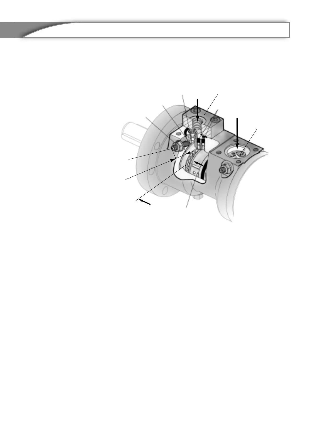
Bild-4 / figure-4
DR
K
T
DM
Q
R
A1
B1
R
D
Anschlussplatte - connection plate
DS
E1