12
Eclipse T500 Actuator, V1, Instruction Manual 902, 12/7/2009
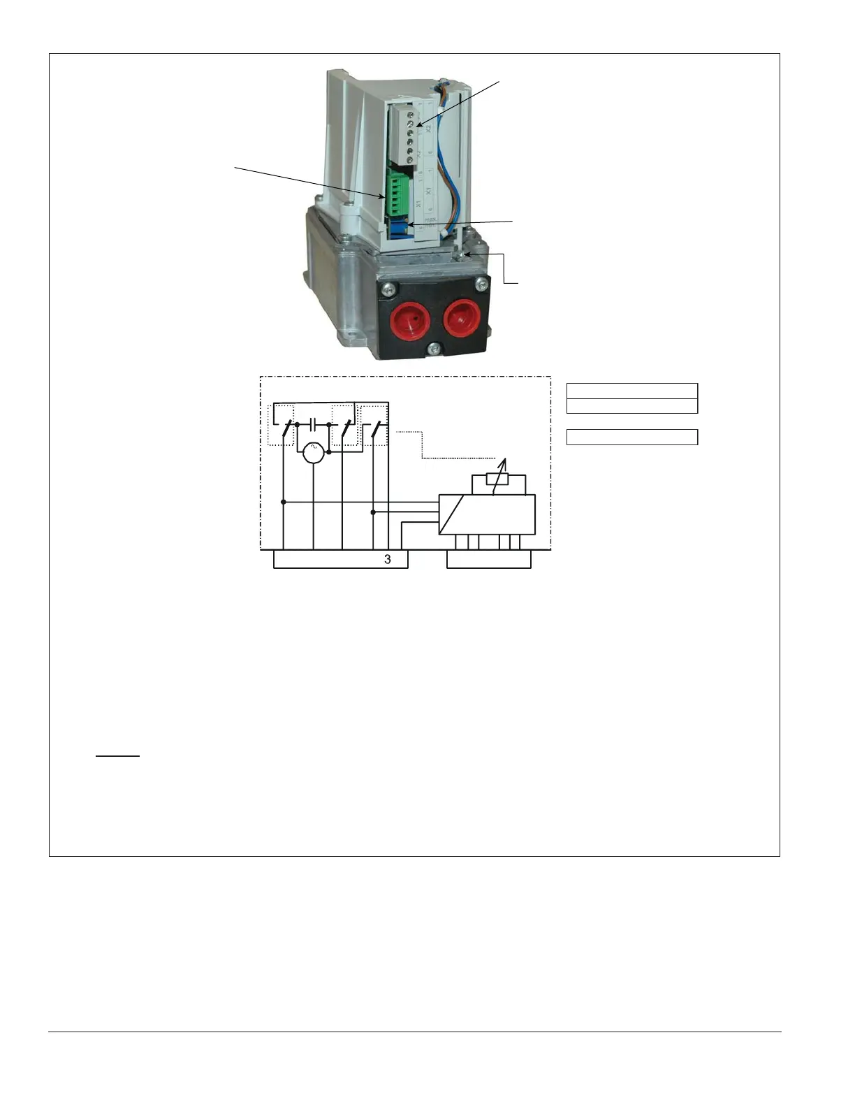
Figure 3.9. Connection Terminals (Electronic Version)
Electronic Version
X1X2
6
5
2 134
5
2
41 6
V
M
VI
I
high RED I
low BLACK V
OFF/IGN GREEN VI
Drive High
Neutral
Drive Low
Drive OFF/IGN*
Common
4 - 20mA
2 - 10V
POT Low
POT Wiper
Position Feedback
Enable
POT High
Connection X1
SELV/PELV
nalog Inputs:
1 2-10 V
2 Common
3 4-20 mA
4 135 Ohm (low)
5 135 Ohm (wiper)
6 135 Ohm (high)
Connector X2
Line Voltage Signals:
1 Drive high
2 Drive low
3 Position reached
4 Drive off/ignition
5 Enable
6 Neutral
Analog Signal Potentiometers:
Maximum Range Adjustment
Minimu
m Range Adjustment
Ground (Protective Earth)
* Only when driving from high position
ign - ignition
NOTE:
Voltage applied at X2-6 Neutral and X2-5 Enable will power the electronic circuits and allows
the analog inputs to drive the actuator. If driving the actuator with the direct voltage connection at
X2-1, -2, or -4 then remove power at X2-5 Enable to avoid conflicting drive currents at the motor.
SELV or PELV depends on the safety class of the connected devices. For PELV, the device is
connected to protective earth (ground).