9
Eclipse T500 Actuator, V1, Instruction Manual 902, 12/7/2009
Use a small flat blade screw driver in the screw slot
corresponding to the cam to be adjusted. Turn the
adjusting screw until the cam pointer is at the desired
degree on the scale. An internal index at the bottom of the
cams shows the current position. For clockwise-to-open
models, use the outer scale marked “R”. For counter
clockwise models, use the inner scale marked “L”. See
“Cam Positions” on page 13.
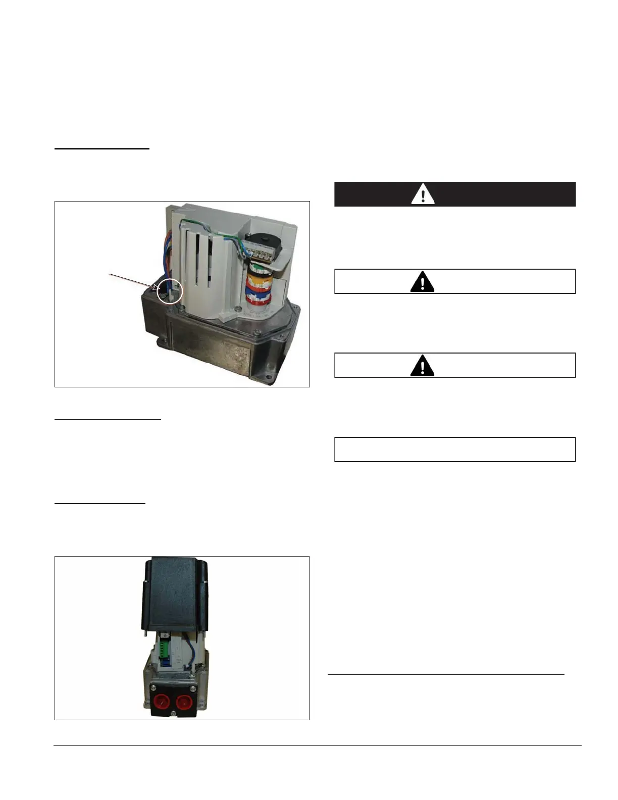
Shaft Disengage
Shaft can be disengaged from the motor and part of the
gear train by pressing pin K1. When the motor starts
driving, then the shaft automatically re-engages.
Figure 3.4.
Auxiliary Contacts
The internal contacts marked AUX are isolated and
voltage-free. Take care not to exceed the contact ratings
listed in the specifications table on page 16. These
contacts can be used for position detection and auxiliary
control.
Actuator Wiring
Access is through the two electrical connectors at the end
of the actuator. Remove the housing cover to access the
terminal strips, as shown in Figure 3.5.
Figure 3.5. Actuator Wiring
Connection Terminals shown in Figure 3.8 and Figure 3.9
shows the wiring diagram for the actuator, while Typical
Applications on Figure 3.11 shows a temperature control
connected to the electronic version.
To install a wire into a terminal, first be sure the terminal is
fully open. Strip the wire insulation back 1/4" (6mm), and
insert the wire. Hold the wire in place while tightening the
terminal screw. Inspect the wire for loose strands and
gently pull it to ensure a secure connection. Use only one
wire per terminal.
Ŷ To reduce the risk of electric shock - Do not
connect to a circuit operating at more than 150
volts to ground.
Ŷ Risk of electric shock - Removal of the housing
cover allows access to conductors carrying
hazardous voltage.
Ŷ The conduit connecting cover is plastic, therefore
bonding to the gound and between conduit fittings
must be provided as part of the installation.
Ŷ Connect only to a flexible wiring system.
Ŷ Use copper conductors only.
Ŷ For supply connections, use No. 16 AWG or larger
wire rated for at least 194°F (90°C).
Ŷ Power to the actuator must be protected for over
current according to the relevent standard, such
as a fuse of maximum 6.3 AT.
Ŷ Wire all class 2 circuits using Types CL3, CL3R,
CL3P or equivalent conductors.
Ŷ Required tightening torques:
• Housing cover: 3.5 Nm
• Cable connecting cover: 2 Nm
Electronic Version, Control Signal Wiring
Connect a 4-20mA signal positive (+) to X1-3 and
negative (–) to X1-2 (GND). Or alternately connect a 0-10
Vdc signal positive (+) to X1-1 and negative (–) to X1-2
Pin K1
The clutch will
engage again
when released
and the actuator
moves.