14
Eclipse T500 Actuator, V1, Instruction Manual 902, 12/7/2009
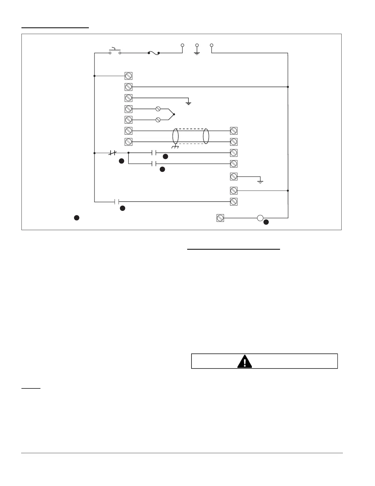
Typical Application
Figure 3.11.
This example shows a method for igniting a burner at a
firing rate higher than its minimum run position.
• A “High” relay makes contact during the purge cycle.
It is controlled from the flame safeguard or customer
control. The actuator drives to the high position as
set by CAM I.
• The “High” contact opens after the purge time, and
the ignition, “IGN” relay makes contact to drive the
actuator to the ignition position as set by CAM VI.
• After the trial for ignition, the normally closed “Auto”
relay breaks its contact to remove supply power
from the “High” and “IGN” relay contacts.
• A normally open “Auto” relay makes contact to
supply power to the enable input X2-5. Then the
actuator follows the analog input on X1-2, X1-3.
• The analog modulation is between CAM I and
CAM V.
NOTE:
The following diagram is an example of how to use
the actuator’s various inputs and outputs. Some devices
shown may be omitted or changed, depending on your
application.
Checklist After Installation
1. Confirm the alignment and tightness of all mechanical
connections.
2. Inspect the terminal wiring for stray wire strands that
might cause a short circuit. Check that the wires are
properly inserted into the terminals and are not loose.
Reinstall the terminal cover.
3. Apply power and verify that the stroke motion is
smooth over its entire range.
4. Record the cam settings for future reference.
Ŷ After wiring, inspect the seal and install the cover
carefully. Make sure cover is seated properly to
seal out water.
Sensor
These components relate to burner sequence (not shown)
High Fire
Temperature
Controller
Electronic
Actuator
L1 GND L2
Power
OnOff
5A Fuse
L1
L2
GND
T/C
+
–
4-20mA
+
–
1
1
1
1
X1-3 (+)
X1-2 (-)
X2-1 (Drive High)
X2-4 (Drive to IGN)
G
X2-5
X2-6
Coil
X2-3
shaft at
position
Auto
1
Auto
1
IGN
(Neutral)
(Enable)
(Feedback)
WARNING