8
Eclipse T500 Actuator, V1, Instruction Manual 902, 12/7/2009
• Ensure the actuator is not exposed to direct sunlight.
• Determine if the butterfly valve (BV) has unrestricted
full rotation or if it has physical stops that limit
rotation to a specific angle. Also, determine the
minimum position, rotation direction to open, and
maximum open position for the BV.
• Check the actuator’s rotation direction and cam
switch adjustments match to the butterfly valve.
Refer to “Cam Positions” on page 13 to identify the
low and high stroke adjustment.
• Make the electrical connections either temporary or
as required by the application and apply power.
Verify for proper and smooth motion over the full
stroke range. Correct any abnormalities before
placing the equipment into operation.
Figure 3.1. Mounting Hole Location
Ŷ Local regulations may require guards and/or
warnings when connecting the actuator to a device
that could cause finger pinching. The actuator stall
torque is at least 10 Nm.
Ŷ Do not attempt to mechanically force the actuator
shaft to rotate. See “Shaft Disengage” on page 9
for procedure.
Ŷ Appropriate electrical fittings must be installed to
maintain seal and environmental ratings.
Ŷ Prevent water from condensation flowing into the
actuator housing through the wiring conduits.
Keep conduits oriented such that gravity will
cause water to flow away from the actuator or
provide a watertight seal in the conduit near the
actuator.
Ŷ If using cables, provide strain relief in
conformance to the relevant standards, such as
DIN EN 60730 and DIN EN 60335.
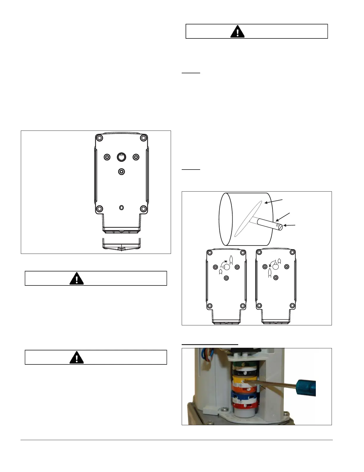
NOTE:
The butterfly valve rotation direction is viewed
from the shaft end connected to the actuator. The slot at
the end of the butterfly valve shaft is parallel to the shutter.
See Figure 3.2. When the shaft is rotated to align the slot
to the pipe direction, the valve is at maximum flow. Eclipse
BVs with the beveled shutter option have a 75 degree
stroke. The minimum positions of these valves physically
stop at about a 15 degree angle when the butterfly shaft is
turned fully counter-clockwise. Therefore, the actuator
must have its low position set to about 15 degrees to
prevent trying to rotate against the physical stop. Final
fine-tuning adjustments to the minimum position can be
made after mounting the actuator to the BV.
NOTE:
The rotating direction of the actuator is viewed into
the shaft. Therefore, the clockwise butterfly valve needs a
counter clockwise actuator.
Figure 3.2.
Cam Adjustment
Figure 3.3.
Connecting Cover Europe
Connecting Cover US
A
A
AA
BB
B
C
WARNING
CAUTION
CAUTION
Shutter
Shaft
Slot is in
line with
the shutter
Clockwise Rotation
Counter-Clockwise
Rotation