3.8 BOILER SAFETY SYSTEMS
The boiler is fitted with the following devices (see section 3.2 for refer-
ences).
1 - I
GNITION FAILURE:
This control signals an ignition failure on the burner 7 seconds
after a lighting failure. The L.E.D. “F” will illuminate to signal the
shutdown status.
The system can be reset by pressing and releasing the button
“H” after checking to make sure that the gas cock is open.
2 - CIRCULATION FAILURE:
This control signals that the safety pressure switch on the primary
circuit has not sensed a pressure of at least 1 bar within 40 sec-
onds of the activation of the circulation pump; the circulation
pump comes to a halt and the red L.E.D. “L” illuminates.
The system may be reset, after re-establishing the correct level of
pressure in the boiler, turning the “A” knob.
3 - O
VERHEATING:
This control shuts off the boiler in the case where the primary cir-
cuit reaches a temperature in excess of 105°C.
The red L.E.D.s “I” and “F” will illuminate to signal this shutdown
status.
The system can be reset waiting a few minutes for the primary
exchanger to cool down and then by pressing and releasing the
“H” button.
4. L
IMESCALE BUILD-UP:
The boiler is equipped with a device that limits the formation of
Limescale in the secondary exchanger by controlling the temper-
ature of the domestic hot water (max 61°C) and also controlling
the temperature of the water in the primary heating circuit which
must not over come the temperature of 72°C.
5. ANTI-FROST DEVICE:
The boiler is equipped with a device that, in the event of the water
temperature going below 5°C, the 3-way diverter valve switches
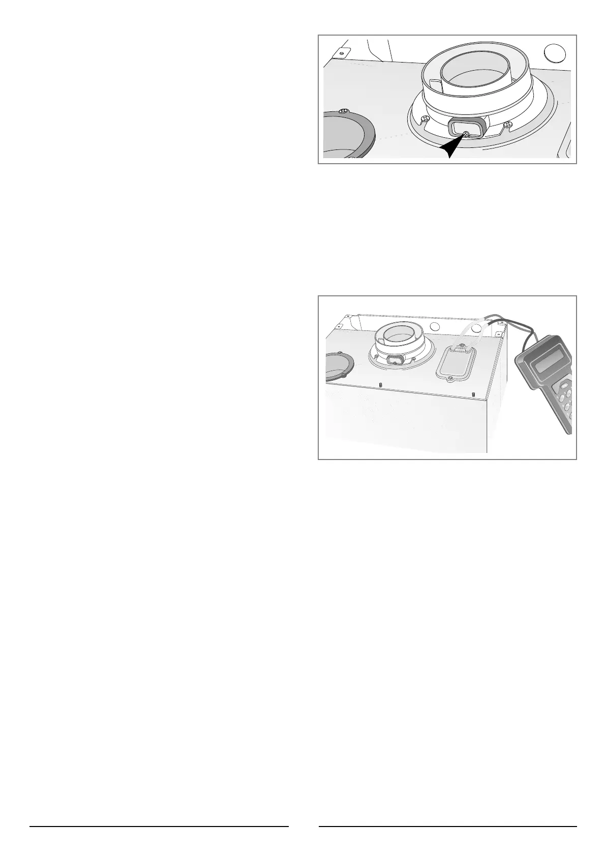
The flue connector has two apertures, readings can be taken for the
temperature of the combustion by-products and of the combustion air,
as well as of the concentrations of O
2
and CO
2
, etc. .
To access these intakes it is necessary to unscrew the front screw and
remove the metal plate with sealing gasket.
The best test conditions, with the maximum heating power, are
achieved by turning the selector knob “C” to the “max” position and
removing the electrical connection to the heating sensor (see section
6.).
3.6 COMBUSTION ANALYSIS
In the boiler, it is possible to monitor the correct operation of the flue
exhaust/air intake, checking for a loss of general pressure in the sys-
tem. Through the use of a differential manometer connected to the test
points of the combustion chamber, it is possible to detect the ∆Pof
operation of the air pressure switch.
The value detected should not be less than 0,55 mbar under conditions
of maximum thermal power in order to allow a correct boiler operation.
3.7 FUME DISCHARGE MONITORING
3.5 OPERATIONALADJUSTMENTS
(See section 3.2 for references) it is possible to:
- Set the temperature of the heating system by adjusting the knob
“C”
- Set the temperature of the domestic hot water by turning knob “B”
- The selector knob “G” allows the user to choose the economy
mode (position “E”) or the comfort mode (position “C”).
The economy mode is the normal state for the operation of the
boiler, as the domestic water is heated.
The comfort mode is a special operating state, because the water
contained in the secondary exchanger and in the primary exchang-
er is maintained in a preheated condition, allowing a quicker deliv-
ery of domestic water when required. The latter is therefore the
more convenient choice.
To access the areas in which adjustments are made, it is necessary to
open the control panel, as indicated in section 3.3, then remove the
rear inspection cover by unscrewing the two screws. Access is thereby
provided to the P.C.B. and to the following components:
1. the power supply cable connector;
2. the fuses;
3. the soft-light potentiometer the setting for which can range from the
minimum thermal power to the maximum;
4. the maximum thermal heating power potentiometer adjustable by
the minimum to maximum power (already calibrated in the factory
to 70% of the maximum thermal power, about 16kW);
5. jumper selector for the ignition delay.
6. the time clock connector.
10
3.4. INITIAL START-UP
THE CHECKS TO BE RUN BEFORE INITIAL START-UP ARE AS FOLLOWS:
1. Make sure that:
- the screw on the automatic air valve has been loosened when the
system is full;
- If the water pressure in the system is below 1 bar, bring it up to the
appropriate level;
- Check to see whether the gas cock is closed;
- Make sure that the electrical connection has been made properly
and that the earth wire is connected to an efficient earthing system;
-
Supply power to the boiler by turning the On/Off switch “A” in position “I”
- the L.E.D. “D” will illuminate - turn the selector knob “C” to the
winter /central heating position. This will start the circulation pump.
Leave the boiler as it is until all of the air has been bled from the
lines. After 7 seconds, the boiler will signal a shutdown due to igni-
tion failure.
- Loosen the cap on the head of the pump to eliminate any air pock-
ets;
- Repeat the procedure for bleeding the radiators of air;
- Open the taps for a brief period;
- Check the system pressure and, if it has dropped, open the filling
loop again to bring the pressure back up to 1 bar.
2. Check the exhaust flue for the fumes produced by combustion.
3. Make sure that all gate valves are open;
4. Turn on the gas cock and check the seals on the connections,
including the one for the burner, making sure that the meter does
not signal the passage of gas. Check the connections with a soap
solution and eliminate any leaks.
5. Press the reset button “A” for the lighting system; the spark will
light main burner. If the burner does not light the first time, repeat
the procedure.
6. Check the minimum and maximum pressure values for the gas
going to the burner; adjust it if needed using the values indicated in
the table section 4 (See the relative section for burner pressure
adjustment within the servicing manual).
 Loading...