8
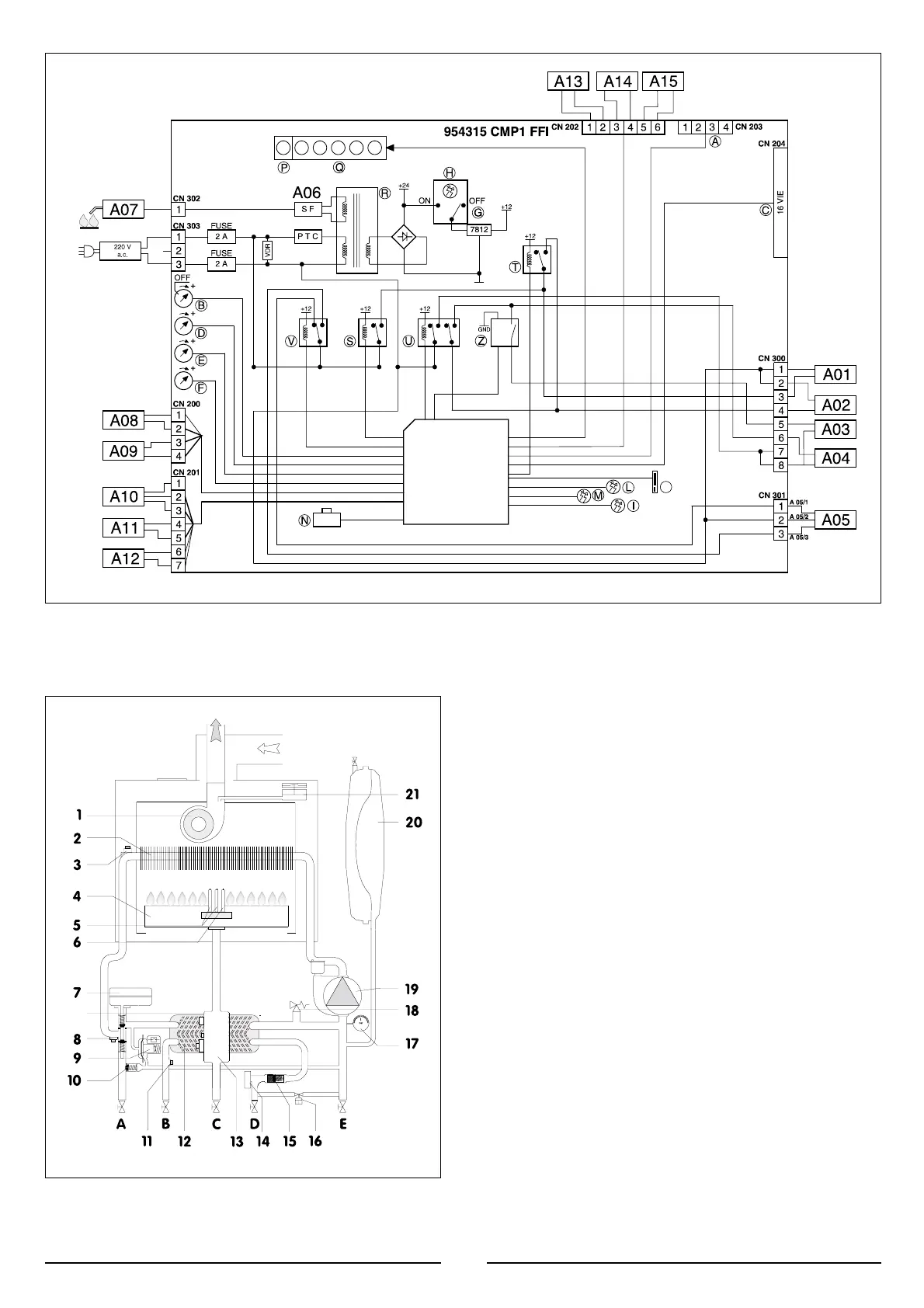
2.12 WATER CIRCUIT DIAGRAM
LEGEND:
1. Fan
2. Main Heat Exchanger
3. Over Temperature Thermostat
4. Burner
5. Ignition Electrodes
6. Detection Flame Electrode
7. Motorised Valve
8. Heating Probe
9. Main Circuit Flow Switch
10. Automatic By-pass
11. Domestic Hot Water Temperature Probe
12. Secondary Heat Exchanger
13. Gas Valve
14. Domestic Hot Water Flow Switch
15. Domestic Water Inlet Filter
16. Water Inlet Valve
17. Manometer
18. Safety Valve 3 bar
19. Circulation Pump with Automatic Air Release Valve
20. Expansion Tank
21. Air Pressure Switch
A. Central Heating Flow
B. Domestic Hot Water Outlet
C. Gas Inlet
D. Domestic Cold Water Inlet
E. Central Heating Return
 Loading...