2.8 WATER CONNECTIONS
F
H
G
The figure below shows the unions for hydraulic and gas connections.
In the hydraulic connection kit you will find more details about that.
Verify that the maximum pressure rate is not more than 6 bar ; if it
results more than 6 bar you have to install a pressure reducer.
The minimum pressure needed for the operation of the devices that
check the production of Domestic hot water is 0,2 bar. It is possible to
add a capacity device on the filter downstream, as shown in the figure.
VIEW OF THE BOILER CONNECTIONS
LEGEND:
A = Central Heating Flow
B = Domestic Hot Water Outlet
C = Gas Inlet
D = Domestic Cold Water Inlet
E = Central Heating Return
F = Filling cock
G = Safety valve discharge
H = Circulation pump fitting screw for trasportation
(to be removed before lighting the boiler up)
- Position the wire in the dope rubber in order it engages on the con-
trol panel.
- The blue wire (neutral) must be connected to the terminal marked
with " N "
- The brown wire must be connected to the terminal marked with " L "
- The yellow, green (earth) wire must be connected to the terminal
marked with " O "
The boiler operates with H type of gases that belong to the second
group (II 2H3+) as shown in the tabel on chapter 4 " Gas Regulation "
In case that it is necessary to change the gas type, see point 4.1
Proceed with the connection provided the circuit is fitted with an isola-
tion valve, as foreseen in the normes in force
In case of a connection with preexistent flues, check that they are per-
fectly cleaned, without any wastes or dirts, as the eventual separation
can obstruct the fume discharge causing dangerous situations.
2.7 GAS CONNECTION
4
For safety purposes, have a competent person carefully check the
electrical system in the property, as the manufacturer will not be held
liable for damage caused by the failure to earth the appliance properly
or by anomalies in the supply of power. Make sure that the residential
electrical system is adequate for the maximum power absorbed by the
unit, which is indicated on the rating plate. In addition, check that the
section of cabling is appropriate for the power absorbed by the boiler.
The boiler operates with alternating current, as indicated in the techni-
cal information table section in 6, where the maximum absorbed power
is also indicated. Make sure that the connections for the neutral and
live wires correspond to the indications in the diagram.
I
MPORTANT!
The connection to the electrical mains must be made as perma-
nent connections (not with removable plugs) and fitted with a
bipolar switch with a minimum contact break of 3 mm.
In the event that the power supply cord must be changed, replace it
with the same specifications (3x0,75 - ø max external section 8mm)
For electrical connections proceed as follows :
- open the control panel as indicated in paragraph 3.3
- Loosen the screws located on the bottom part of the control to enter
the terminal board.
- Take the wire supplied with the boiler from the free feedthrough and
lead the new wire in the same free feedthrough, then fix it with the
cable clamp.
- Lead the new wire in the rubber " A " already led in the earth wire.
Position the template on the wall where the boiler is going to be instal-
led and use a level to make sure that the top strip is perfectly level.
For additional information, please consult the instructions contained in
the connection kit and the flue kit.
2.6 ELECTRICAL CONNECTION
2.5 MOUNTING THE APPLIANCE
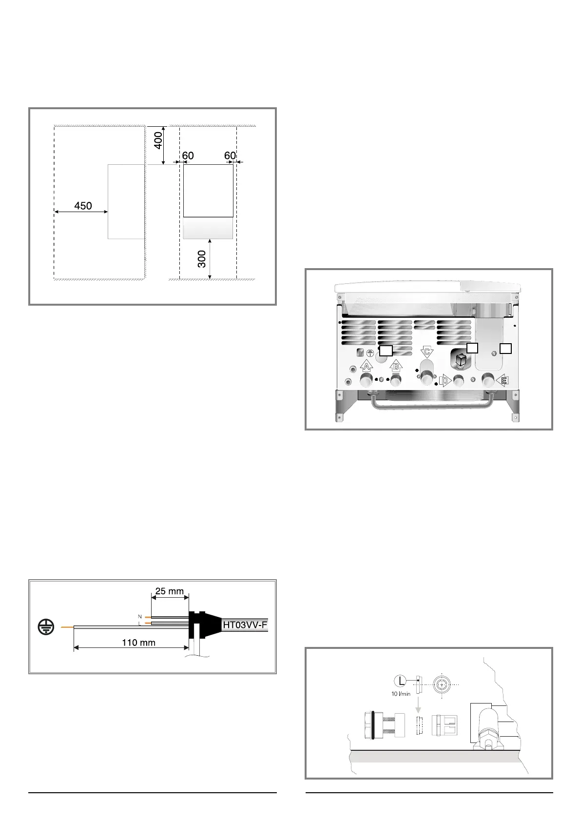
In order to allow for access to the interior of the boiler for main-
tenance purposes, the boiler must be installed in compliance
with the minimum clearances indicated
2.4 CLEARANCES
 Loading...