3
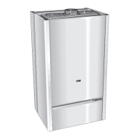
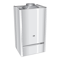
1.2 OVERALL VIEW
THE INSTALLATION AND INITIAL START UP OF THE BOILER MUST BE CARRYED
OUT BY
AUTHORISED PERSONNEL ONLY, IN COMPLIANCE WITH NATIONAL,
LOCAL, AND ALL OTHER INSTALLATION STANDARDS WHICH ARE CURRENTLY IN
EFFECT.
2.2 SITING THE APPLIANCE
2.1 INSTRUCTIONS BEFORE INSTALLATION
2. INSTALLATION
This is an appliance for the production of Domestic hot water reaching
a temperature lower than the boiling temperature .
This appliance must be connected to a suitable heating system and to
the Domestic hot water distribution network, according to its output and
its performances.
Before connecting the boiler, you must :
- Carefully clean the pipes in the system to prevent residual foreign
matter from compromising the operation of the boiler.
– Make sure that the boiler is designed to operate with the type of gas
which is available. Simply read the label on the packing.
– Check that the flue has sufficient draft, does not have sections with
bottlenecks and that other appliances do not discharge exhaust into the
flue – unless the flue is specially designed to serve more than one user
or appliance in accordance with current safety standards and codes.
In case of connection with preexistent flues, check that they are perfec-
tly cleaned, without any wastes or dirts, as the eventual separation can
obstruct the fume discharge causing dangerous situations.
G) The type C appliances (in which the combustion circuit, air
vent intake and combustion chamber are air – tight with respect to
the room in which the appliance is installed) can be installed in
any type of room.
There are no limitations with respects to ventilation and the volume of
the room itself.
The boiler must be installed on a solid, permanent wall to prevent
access to the electrical parts (when live) through the aperture on the
back frame.Not to compromise the correct operation of the boiler, the
room where it is going to be installed has to be suitable to the tempera-
ture limit of the operation and be protect from atmospheric agents. The
location must permit adequate space for servicing and air circulation
around the appliance as indicated in paragraph 2.4.
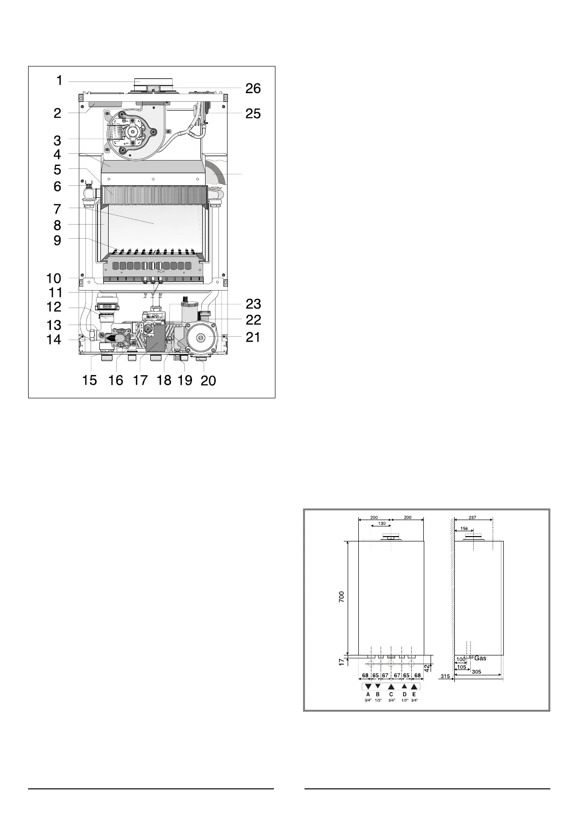
LEGEND:
A = Central Heating Flow
B = Domestic Hot Water Outlet
C = Gas Inlet
D = Domestic Cold Water Inlet
E = Central Heating Return
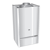
2.3 OVERALL DIMENSIONS
LEGEND:
1. Flue connector
2. Air intake
3. Fan
4. Combustion chamber hood
5. Main heat exchanger
6. Safety thermostat
7. Combustion chamber
8. Combustion chamber insulation panel
9. Burner
10. Detection electrode
11. Ignition electrodes
12. Motorised diverter valve
13. Main circuit temperature probe
14. Main circuit flow switch
15. Domestic hot water temperature probe
16. Gas valve
17. Spark generator
18. Domestic hot water flow switch
19. Domestic cold water inlet filter
20. Secondary heat exchanger
21. Circulation pump with automatic air release valve
22. Safety valve (3 bar)
23. Flow Detector
24. Expansion vessel
25. Air pressure switch
26. Combustion analysis intakes
 Loading...