7
2.11 ELECTRICAL DIAGRAM
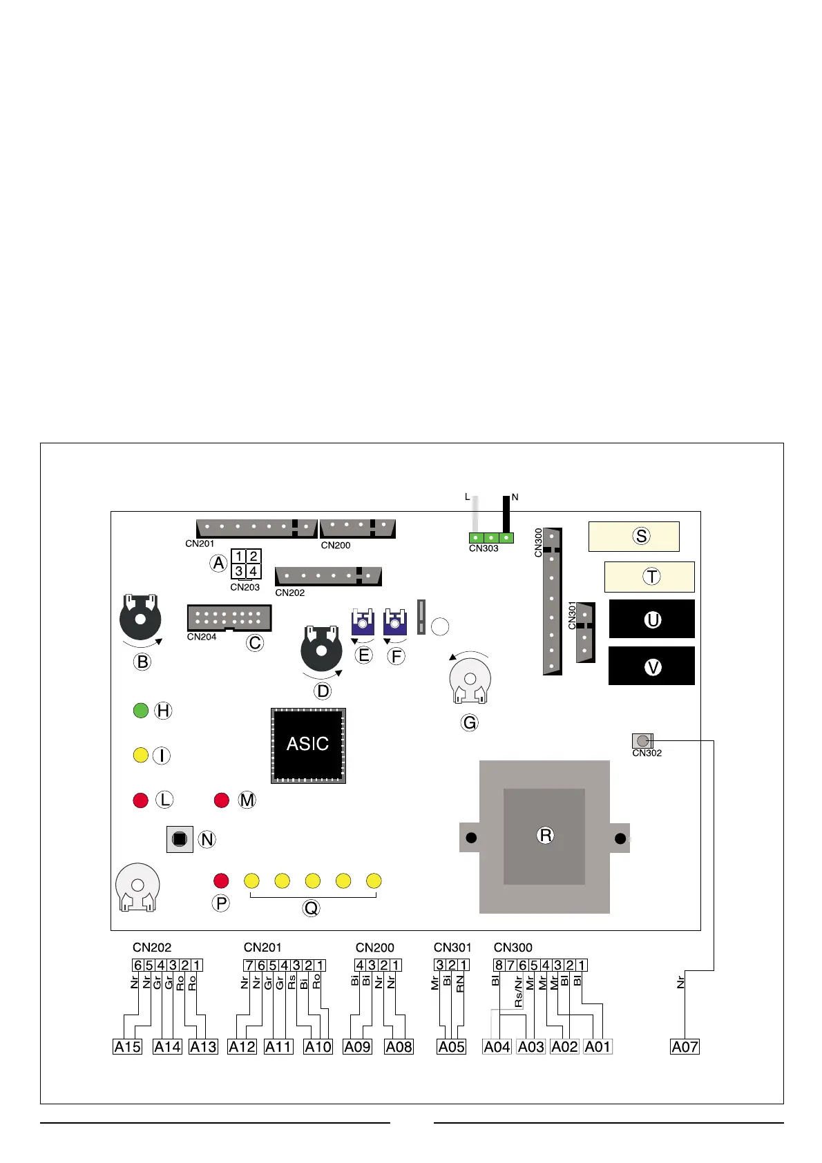
LEGEND:
A = Time Clock Connector
B = Central Heating Selection (Winter) and temperature
Adjustment
C = Diagnosis connector
D = Domestic Hot Water Temperature Adjustment
E = Soft-start ignition
F = Maximum Heating Adjustment
G = On/Off Switch
H = On/Off L.E.D.
I = Fume Sensor L.E.D.
L = Ignition Failure (Lockout) L.E.D.
M = Low System Water Level/Lack of Circulation L.E.D.
N = Reset Button
P = Overheat L.E.D.
Q = Temperature L.E.D.s
R = Transformer
S = Circulation Pump Relay
T = Fan Relay
U = Gas Valve Relay
V = Motorised Diverter Valve Relay
Z = Spark ignition
U = Late ignition device
A01 = Circulation Pump
A02 = Fan
A03 = Spark Generator/Gas Valve Supply
A04 = Gas Valve Supply
A05 = Motorised Diverter Valve
A06 = Flame Detection Circuit
A07 = Flame sensor
A08 = heating probe
A09 = Domestic Hot Water Temperature Probe
A10 = Domestic Hot Water Flow Switch
A11 = Heating Flow Switch
A12 = Modulator
A13 = Flue Air Pressure Switch
A14 = Safety Thermostat
A15 = External (Room) Thermostat/time programmer
Colours:
Gry = Grey
Wh = White
Pnk = Pink
Brn = Brown
Bl = Blue
Blk = Black
Rd/Blk = Red/Black
 Loading...