9
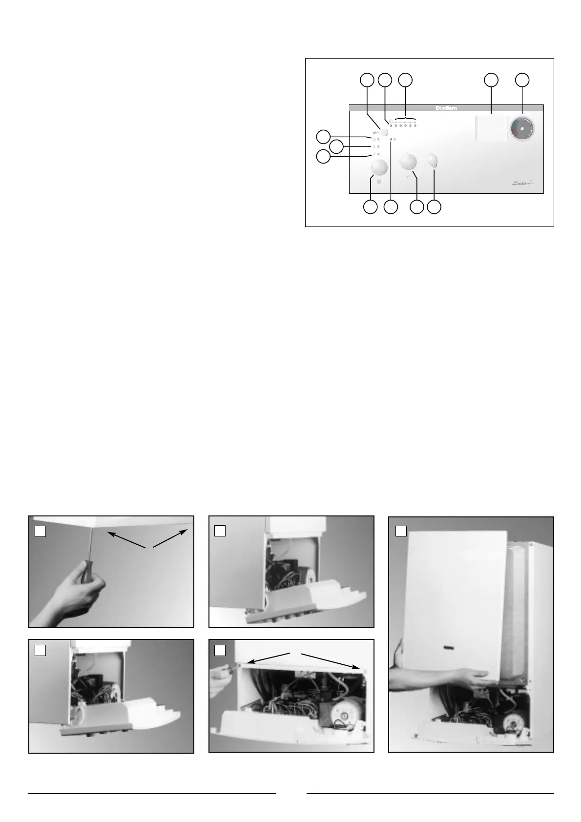
3.2 CONTROL PANEL
3. COMMISSIONING
3.1 INITIAL PREPARATION
Preliminary electrical system checks to ensure electrical safety
must be carried out by a competent person i.e. polarity, earth con-
tinuity, resistance to earth and short circuit.
The gas output, the voltage and the frequency must coincide with the
data on the boiler plate
Filling the Heating System:
- open the pressure relief valves of the installation radiators
- Gradually open the water inlet valve and close the pressure relief
valve when the water comes out.
- Close the water inlet valve when the indicated pressure on the ther-
mohydrometer is at 1 bar
G
AS SUPPLY:
- Open the gas cock (supplied with the connection kit) to the appliance
and check the gas connector on the appliance for leaks.
IMPORTANT!
BEFORE ANY INTERVENTION IN THE BOILER IT IS NECESSARY
TO SWITCH OFF THE ELECTRICAL SUPPLY TURNING THE
EXTERNAL SWITCH ON " O " ( OFF ).
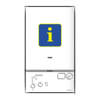
LEGEND:
A - On/Off knob
B - Domestic hot water temperature adjustment knob (summer)
C - Water ignition failture L.E.D. (red)
D - Central heating selection (winter) and temperature adjustment knob
E - Heating system working L.E.D. (green)
F - Fume sensor L.E.D. (yellow)
G - Ignition failure (lockout) L.E.D. (red)
H - Ignition failure (lockout) and/or overheat reset button
I - Overheat L.E.D. (red)
L - Central heating temperature L.E.D (yellow)
M - Arrangement for programming time clock (optional)
N - Hydrometer
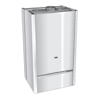
3.3 REMOVING THE FRONT PANEL
In order to access the inside of the boiler, it is necessary to unscrew the
fastening screws “A” of the control panel located on the lower part of
the panel itself.
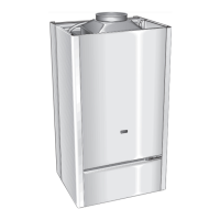
The control panel moves downward and when pulled forward rotates
on two lateral hinges.
The panel stays in a semi-horizontal position, which allows access to
the inner parts of the boiler.
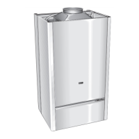
In order to increase the maneuvering space, it is possible to raise the
control panel and rotate it to a fully horizontal position.
1
2
5
3 4
A
B
 Loading...