2.10 ROOM THERMOSTAT CONNECTION
To connect a room thermostat, it is necessary to:
1 open the control panel as indicated in section 3.3.
In calculating the lengths of the pipes, the
maximum length “L” must also take into con-
sideration the values for the exhaust/air intake
end terminals, as well as 90° elbows for coaxi-
al systems.
The C52 types must comply with the following
requirements:
1 - The exhaust/ air intake pipes must have
the same diameter of ø 80 mm.
2 - If elbows are to be inserted into the air
intake and/or exhaust system, the calcu-
lation of the overall length must take into
consideration the values for each elbow.
3 - The exhaust pipe must protrude by at
least 0.5 m above the top of the roof in
the event that it is located on the opposite
side to the side with the air intake (this
condition is not obligatory when the air
intake and exhaust are located on the
same side of the building).
TWIN PIPE SYSTEMS
COAXIAL SYSTEMS
Exhaust
Type
C12 (xy)
C32 (xy)
C42 (xy)
C52 (xy)
C82 (xy)
Restrictor
ø 43 mm
L max = 11,5 m
L max = 11,4 m
Maximum
Extension
Exhaust/Air
43 m
40 m
NO
Restrictor
L min = 11,5 m
L max = 43 m
L min = 11,4 m
L max = 40 m
Risk of Condensation Forming
Twin Pipe
System
ø 80/80
Piping not insulated
ø 43 restrictor no
4,3 m 6,9 m
4,3 m 6,9 m
Piping insulated
ø 43 restrictor no
5,7 m 21,7
5,7 m 21,7
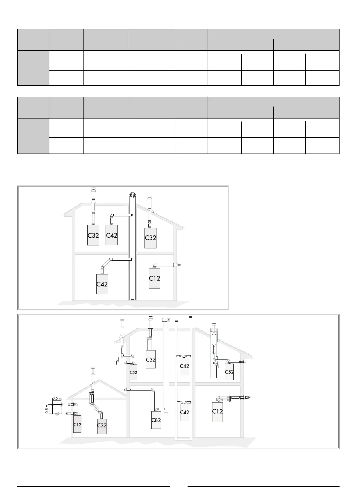
L= Sum of the total length of exhaust + air intake piping.
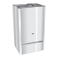
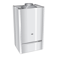
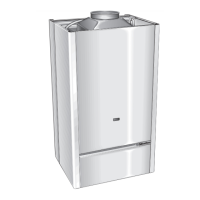
The diagrams illustrate some of the various designs for coaxial or twin pipe flue systems.
For further information on discharge/ventilation accessories, see the F
LUE PIPE ACCESSORIES MANUAL.
6
2 Insert the thermostat cable through the cable grommet and fasten it
by means of the cable-clamp provided by removing the link.
Exhaust
Type
C12 (xy)
C32 (xy)
C42 (xy)
C52 (xy)
C82 (xy)
Restrictor
ø 41 mm
L max = 38 m
L max = 34 m
Maximum
Extension
Exhaust/Air
62 m
54 m
NO
Restrictor
L min = 38 m
L max = 62 m
L min = 34 m
L max = 54 m
Risk of Condensation Forming
Twin Pipe
System
ø 80/80
Piping not insulated
ø 41 restrictor no
8 m 11 m
8 m 11 m
Piping insulated
ø 41 restrictor no
19 m 31 m
19 m 31 m
Linda
+
24 CS CPR
Linda
+
28 CS CPR
 Loading...