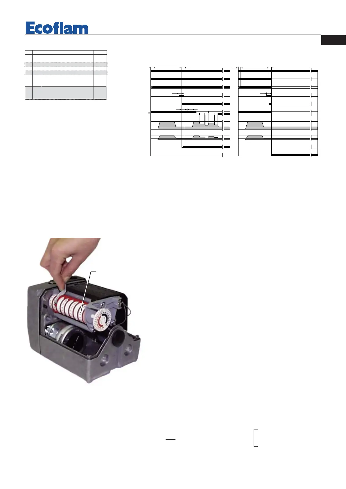
LANDIS & STAEFA SQM 50.481A2 AIR DAMPER MOTOR
Remove cover to gain access to the adjusting cams.The cams are to be adjusted through the suitable key provided for.
Description:
Cam VIII
is never used
I - High flame operating opening position adjusting cam (Light-Oil /Gas).
II - Limit switch for the air damper position at burner’s shut down.
III - Ignition flame opening position adjusting cam (Gas).
IV - Ignition flame opening position adjusting cam(Light-Oil).
V - Low flame operating opening position adjusting cam (Gas).
VI - Low flame operating opening position adjusting cam (Light-Oil).
VII - Not used cam.
VIII - Not used cam.
Multicalor 300.1-400.1 PR/PR
CALCULATING THE BURNER CAPACITY
To calculate the burner's capacity in kW, proceed as follows: Check the gas flow rate (in liters)
on the counter and the time of the reading in seconds.
Proceed with the calculation using the following formula: x f = kW
e
sec
e = Litres gas
sec = Time in second
G20 = 34,02
G30 = 116
G31 = 88
f
LANDIS & STAEFA, Model LFL1.622 - LFL1.333 OPERATING CYCLE
The control box starts the burner
fan, to carry out the prepurging of
the combustion chamber, and
cheks the vent air pressure throu-
gh the air pressure switch. At the
end of prepurging, the ignition
transformer cuts-in and generates
a spark between the electrodes. At
the same time the two gas valves
open (Vs safety valve and Vl working valve). The total safety, in case of missed ignition or casual burner's flame-out, is
granted by a ionisation probe which cuts-in and sets the burner shutdown within the safety time. In case of gas lack or a
major pressure drop, the minimum air pressure switch shuts down the burner.
Ref. Description
t1 Duration Waiting time for confirmation
of air pressure
t2 Preventilation time
t3 Safety time
t4 Pressurizing time
t5 Time for enabling operation of the
main gas valve on minimum capacity
t6 Time for enabling operation of the
main gas valve on maximum capacity
Duration
8”
66”(36”)
2”
4”
10”
10”