The data, information and descriptions, and the technology described herein are the exclusive intellectual property of Ecotechnics S.p.A. and constitute industrial
secrets. Said information is communicated in strict confidentiality; said information may be used only for the purpose for which it is communicated; said information
may not be divulged, communicated, or revealed to third parties and/or reproduced by any means for any reason whatsoever; said information is protected under
applicable Italian competition and industrial property law.
Service manual VA500-VA750 ed.1 ver.5.05 [MANU360.SA0].doc pag.35 - 18/10/2005
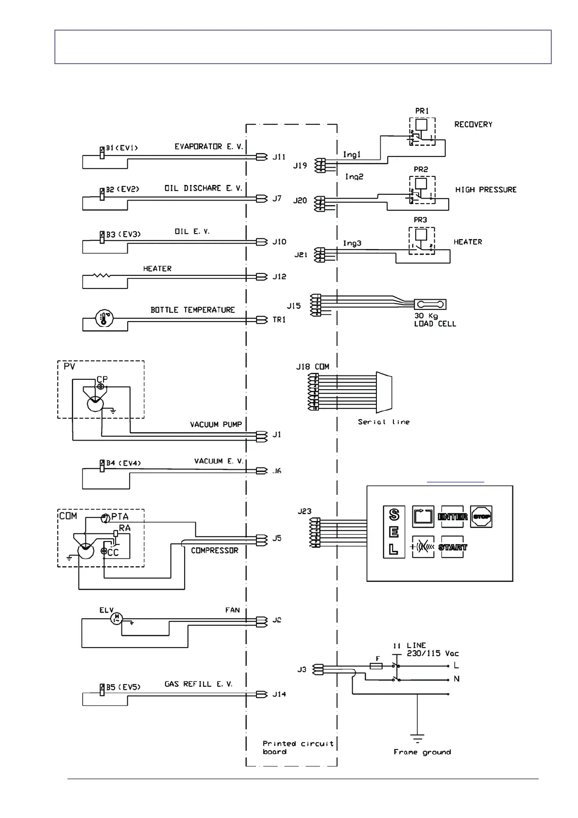
WIRING DIAGRAM
I1 LINE : General switch
F : Fuse 240V/8A
PR1 : low pressure switch
PR2 : Safety pressure switch
PR3 : heater pressure switch (*)
Ing1 : Recovery pressure switch (PR1)
Ing2 : safety pressure switch (PR2)
Ing3 : Heater pressure switch (PR3) (*)
30kg LOAD CELL: refrigerant bottle load cell
HEATER: refrigerant bottle heater (*)
PV : vacuum pump
CP : vacuum pump condenser
COM : compressor
CC : compressor condenser
RA : Current relay opens at end of start-up
PTA : Thermo-amperometric protection
ELV : Electric fan
TR1: Bottle temperature probe
B1,….e B5 : solenoid valve
J1-J21: electronic board jumper
(*) ONLY MODEL XK360
*
*
*