7
1. TURN OFF WATER SUPPLY
a. Close the main water supply valve near the well
pump or water meter.
b. Shut off the electric or fuel supply to the water
heater.
c. Open high and low faucets to drain all water from
the house pipes.
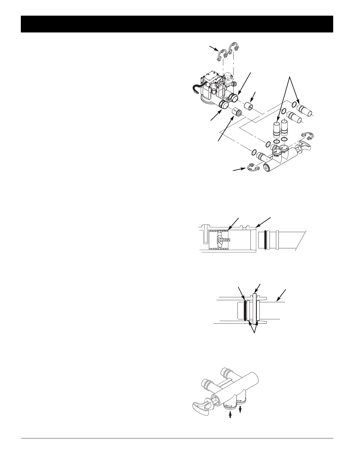
2. INSTALL BYPASS VALVE AND/OR
PLASTIC ADAPTOR / COPPER TUBE:
a. If installing a single bypass valve, push the bypass
valve, with lubricated o-ring seals in place, into the
valve inlet and outlet ports (See Figures 5 & 8).
- OR -
b. If installing a 3-valve bypass system, slide plastic
installation adaptor and copper tube, with lubricat-
ed o-ring seals in place, into the valve inlet and
outlet ports, respectively (See Figures 6 & 8).
c. Be sure the check valve is in place in the valve
inlet, with the flow arrow pointed inward, as shown
in Figure 8.
d. Be sure the turbine support is in place in the valve
outlet, as shown in Figure 9.
e. Snap the two large plastic clips in place on the inlet
and outlet ports, from the top, down (See Figure
10). Be sure they snap into place. Pull on the
bypass valve, copper tube or plastic adaptor, to
make sure they are held securely in place.
3. COMPLETE PLUMBING TO AND FROM
THE FILTER
Using the “Typical Installation Illustration” on page 6
as a guide, observe all of the following cautions while
you connect inlet and outlet plumbing:
= Be sure incoming, unfiltered water is directed to
the valve INLET port.
= Be sure to install the included check valve on
the INLET pipe, immediately upstream of the filter,
as shown in the “Typical Installation Illustration” on
page 6. Note the direction of the flow arrow on the
check valve.
= Be sure to install bypass valve(s).
= If making a soldered copper installation, do all
sweat soldering before connecting pipes to the fil-
ter fittings. Torch heat will damage plastic parts.
= Use pipe joint compound on all external pipe
threads.
= When turning threaded pipe fittings onto plastic fit-
tings, use care not to cross-thread.
= Support inlet and outlet plumbing in some manner
(use pipe hangers) to keep the weight off of the
valve fittings.
Turbine
Support
Valve
Outlet
FIG. 9
FIG. 10
O-ring
Clip
Cross section of
valve inlet or outlet
Bypass valve,
copper tube or
plastic adaptor
Snap clips into place between
larger diameter rings
FIG. 11
Turn the bypass
valve downward if
connecting to floor
level plumbing
INLET
OUTLET
FIG. 8
INLET
OUTLET
Clip (2)
Bypass Valve
Clip (2)
Turbine
Support
1” Copper Tube
(install in filter valve
or bypass valve)
ECOWATER
S Y S T E M S
Installation
Check Valve
(note direction
of flow arrow)